
Last updated: July 22, 2026
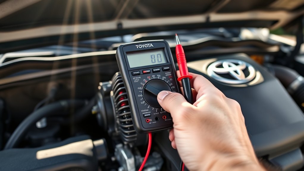
To test a Toyota Tacoma alternator with a multimeter, first confirm the 12-volt battery is fully charged. Then compare DC voltage directly across the battery posts with the engine off, idling, and under high electrical load at 2,000 RPM. A resting battery should measure approximately 12.6 volts, while a healthy charging system delivers 13.7 to 14.7 volts under load. However, on newer Tacomas equipped with computer-controlled smart charging, understanding system operating logic is essential before condemning the alternator. These mechanical alternator testing steps apply strictly to non-hybrid Tacomas with belt-driven alternators.
Quick Answer: Tacoma Alternator Multimeter Benchmarks
- Engine Off (Resting Battery): ~12.6V DC (100% charged); below 12.2V indicates a discharged battery that must be charged before testing.
- Engine Idling (Normal Charging): 13.7V to 14.7V DC (DENSO output range is 13.0V to 15.0V at ~2,000 RPM).
- Smart Alternator Note (3rd & 4th Gen): Voltage may drop to 12.8V–13.2V at idle when the battery is full. Turn on high beams and AC blower to force maximum charging mode.
- Max Circuit Voltage Drop: ≤ 0.20V DC on both the positive and negative ground sides.
- AC Ripple (Diode Test): ≤ 0.05V AC is healthy; ≥ 0.10V–0.30V AC indicates bad rectifier diodes.
Key Takeaways
- A resting 12-volt battery must read near 12.6 volts before evaluating alternator performance.
- Modern 3rd Gen (3.5L) and 4th Gen (2.4L Turbo) Tacomas utilize ECM-controlled smart charging; always apply electrical loads (high beams, blower fan) to verify output.
- Always inspect the 120A/140A ALT fusible link and 7.5A ALT-S fuse in the engine bay fuse box before assuming an alternator is defective.
- At ~2,000 RPM under load, DENSO specifies an output range of 13.0V to 15.0V with no more than a 0.2V voltage drop across either side of the circuit.
- Never disconnect a battery terminal while the engine is running; the resulting voltage surge can destroy sensitive onboard ECUs and sensors.
- For i-FORCE MAX hybrid Tacomas, the 12V battery is charged via an electronic DC-DC converter, not a conventional belt-driven alternator. Never probe orange high-voltage wiring.
At a Glance
| Time Required | 15 to 25 minutes |
| Difficulty | Beginner to intermediate |
| Tools Needed | Digital multimeter with alligator clips, safety glasses, mechanic gloves, flashlight, wire terminal brush |
| Model Scope | Toyota Tacoma (1995–2026 Gas Models: 2.4L, 2.7L, 3.4L, 4.0L, 3.5L, 2.4L Turbo) |
| Estimated Cost | $0 DIY (Free if you own a multimeter; parts stores offer complimentary bench testing) |
What Can a Toyota Tacoma Alternator Test Tell You?
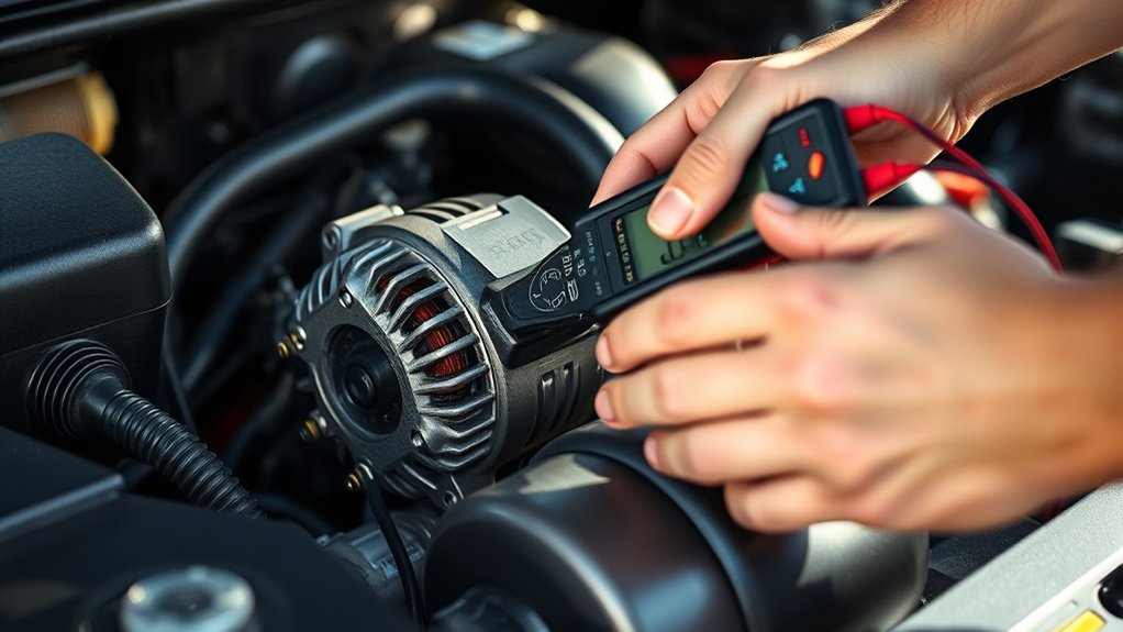
On a conventional gas-powered Toyota Tacoma, the engine-driven alternator generates electrical energy to operate onboard vehicle systems and continuously replenish the 12-volt starting battery while the engine runs. A malfunctioning charging system leads to distinct operational failures: undercharging causes sluggish starting, dimming headlights, accessory shutdown, and battery drain, while sustained overcharging (>15.0V) can overheat the battery electrolyte and damage sensitive control modules.
Testing with a digital multimeter provides a fast, non-invasive diagnostic baseline by measuring resting battery potential, operating charging voltage under dynamic loads, circuit resistance, and internal diode rectification health. According to Fluke’s automotive battery testing guidance, a healthy 12V lead-acid or AGM battery should read ~12.6V DC at rest, while a functioning charging system produces between 13.7V and 14.7V DC during normal operation.
Tacoma Generation Note: 1st Gen (1995–2004) and 2nd Gen (2005–2015) Tacomas feature straightforward internally regulated DENSO alternators. 3rd Gen (2016–2023) 3.5L V6 and 4th Gen (2024–2026) 2.4L Turbo models utilize an Engine Control Module (ECM) variable charging system that modulates alternator output based on real-time battery temperature and electrical demand.
Which Tools Do You Need to Test a Tacoma Alternator?
Accurate electrical diagnostics require basic, dependable tools. A digital multimeter (DMM) with accurate DC voltage, low AC millivolt resolution, and minimum/maximum capture capability is the core instrument required.
| Tool Type | Purpose | Recommended Specification |
|---|---|---|
| Digital Multimeter | Measures resting DC voltage, loaded charging output, and AC ripple | CAT III rated, auto-ranging, DC/AC voltage, MIN/MAX mode, alligator probe attachments |
| Battery Conductance Tester | Validates battery Cold Cranking Amps (CCA) and internal state-of-health | Digital 12V load or conductance analyzer matching your Tacoma battery CCA rating |
| Safety Glasses & Gloves | Protects against battery acid splashing, electrical sparks, and moving belts | ANSI Z87 eye protection and heat/chemical-resistant mechanic gloves |
| Inspection Flashlight | Assists in inspecting serpentine belt tension, wiring harnesses, and ground straps | High-output LED work light or hands-free headlamp |
[Products Worth Considering]

The ANCEL BA101 helps diagnose 12V batteries quickly with clear readings for battery health, charge level, voltage, CCA, cranking, and charging system performance. Designed for a wide range of vehicles and battery types, it offers easy-to-read results, reliable clamp connections, and built-in protection to make testing safer and more convenient.

This automotive circuit tester checks low-voltage DC systems from 3-65V, making it useful for diagnosing headlights, taillights, fuses, sockets, and other vehicle wiring issues. The digital backlit display provides clear voltage readings with fine accuracy, while the bidirectional polarity indicator helps you test from either ground or positive. Built with a durable probe, insulated tip, and extra-long spring wire, it is designed for dependable everyday use in automotive and household electrical work.
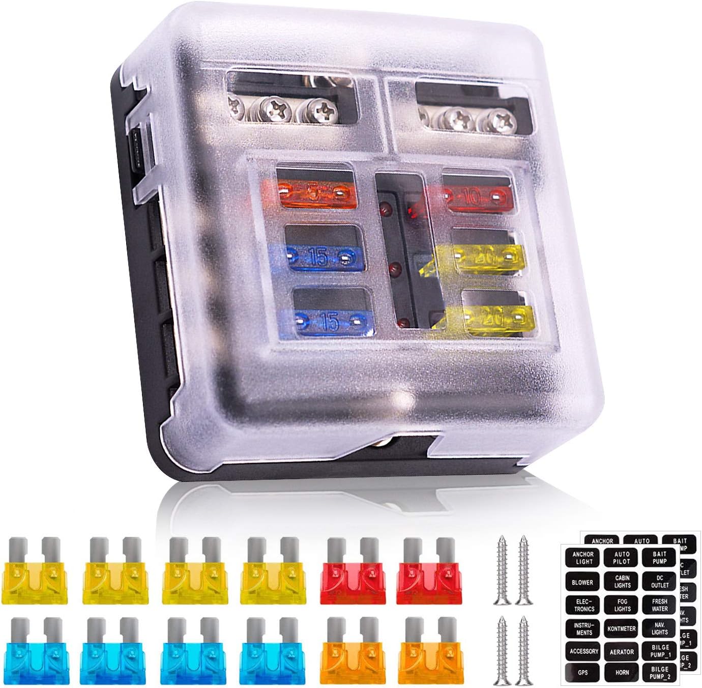
This 6-way fuse block provides organized circuit protection for marine, automotive, boat, truck, and other 12V or 24V electrical systems. Built with a fire-resistant housing and a ground bus, it helps keep wiring neat while the LED indicators quickly show when a fuse has blown for fast troubleshooting. It includes assorted blade fuses, labels, and mounting screws for an easier installation.
Recommended Multimeter Features
Select a digital multimeter that measures DC voltage with at least 0.01V resolution within the 10V–20V range. A dedicated AC millivolt setting is essential for evaluating rectifier diode ripple. Ensure your test leads are completely free of cracked insulation and have clean, tight probe tips. Using insulated alligator clip adapters is strongly recommended to allow hands-free readings when testing near moving pulleys and engine fan blades.
Additional Inspection & Cleaning Tools
Have a wire battery terminal brush, a 10mm socket or wrench (for battery clamps), and a belt tension gauge ready. If battery terminals show visible oxidation or corrosion, cleaning the mating surfaces before taking measurements is necessary to prevent false voltage-drop readings.
Safety Warning: Automotive lead-acid batteries emit flammable hydrogen gas during charging and contain corrosive sulfuric acid. Never create sparks near battery posts, remove jewelry before working near the alternator B+ terminal, and keep hands, clothing, and multimeter leads clear of rotating serpentine belts and cooling fans.
How Do You Prepare a Tacoma for a Multimeter Test?
Park your truck on level ground, shift into Park (or Neutral for manual transmissions), engage the emergency parking brake firmly, and turn the ignition switch completely OFF. Switch off all exterior lights, interior dome lights, climate control blowers, seat warmers, and aftermarket audio accessories.
Removing Surface Charge: If the vehicle was driven within the past 30 minutes or recently connected to a battery charger, turn the high-beam headlights on for 60 seconds without starting the engine. Turn the headlights off and wait approximately 2 minutes. This removes artificial surface charge and allows the battery to settle to its true chemical resting voltage.
Perform a thorough visual inspection under the hood:
- Battery Terminals: Ensure positive and negative battery clamps are fully seated and tight (cannot be twisted by hand). Clean away white or blue-green sulfate powder using a baking soda and water mixture.
- Fusible Links & Fuses: Open the engine compartment fuse block and inspect the clear window on the large ALT fusible link (120A or 140A depending on model year and towing package). Verify that the 7.5A ALT-S fuse is intact.
- Serpentine Drive Belt: Check the alternator drive belt for glazing, cracking, fraying, oil saturation, or slack. A slipping belt will prevent the alternator from generating rated amperage under load.
- Wiring & Plugs: Inspect the alternator rear wiring harness, ensuring the multi-pin regulator connector is clicked in firmly and the insulated rubber boot covers the main B+ output stud.
Per DENSO charging system diagnostic protocols, mechanical drive integrity and clean electrical connections must be confirmed before replacing charging hardware.
How to Test a Toyota Tacoma Alternator With a Multimeter
[Products Worth Considering]

This automotive test light combines a bright LED voltage display with quick polarity indication for fast, accurate circuit checks in a wide range of vehicle systems. It helps diagnose battery, charging, lighting, and fuse issues with a sharp stainless probe, long spring wire, and easy-to-use alligator clip for efficient troubleshooting.
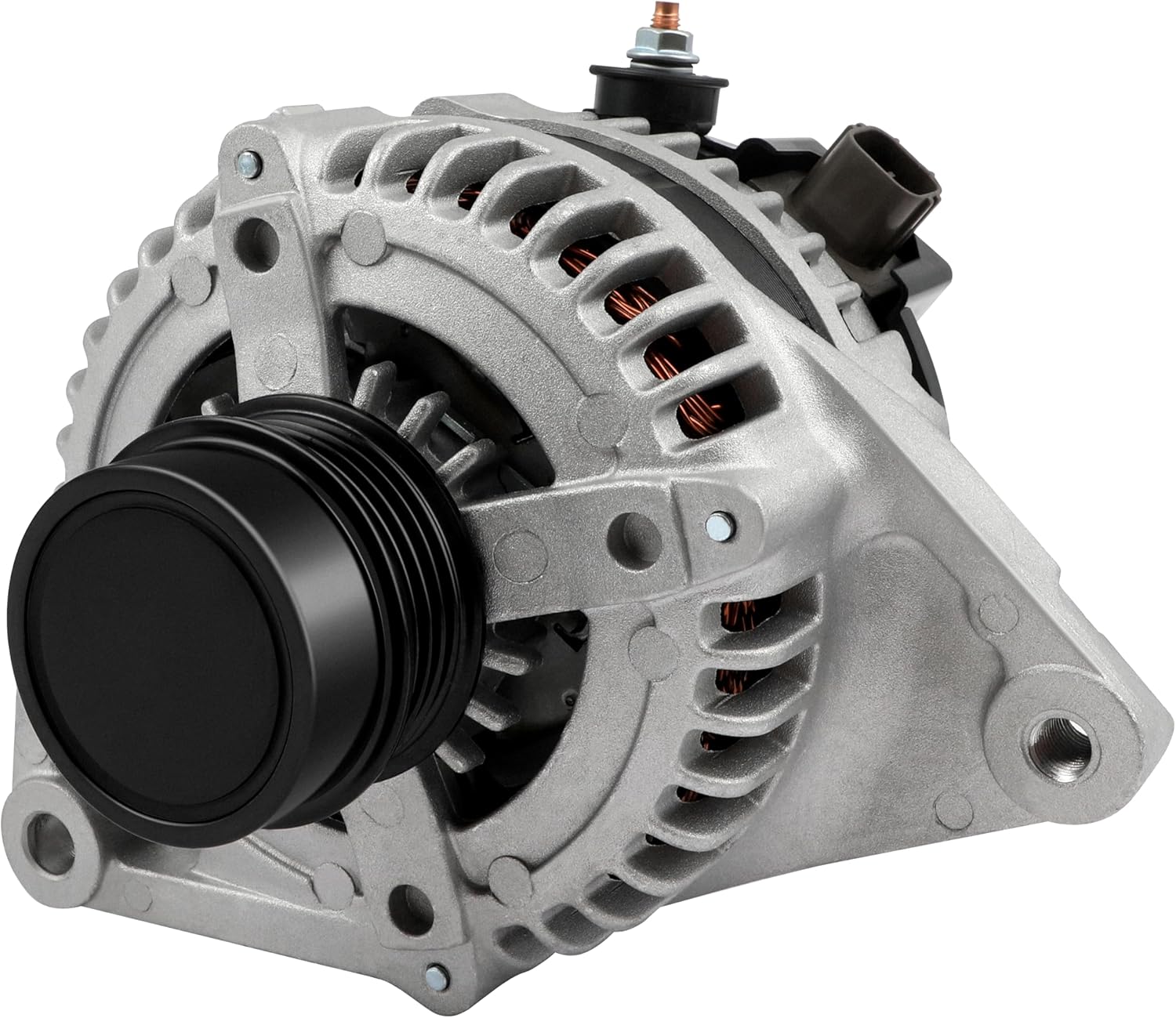
This high output alternator is designed to fit select Toyota, Scion, and RAV4 2.5L applications, delivering reliable charging performance for everyday driving. Built with a 12-volt, 100-amp design and precision-engineered components, it helps support battery recharge, stable electrical output, and consistent operation when your vehicle shows signs of charging issues.
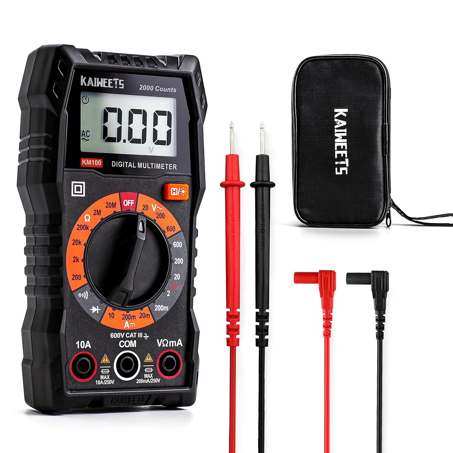
This KAIWEETS digital multimeter is a versatile tool for measuring AC/DC voltage, DC current, resistance, continuity, and diodes in home, automotive, and electrical applications. It includes pre-installed batteries, a carrying case, test leads, data hold, backlight, and overload protection for easier and safer everyday testing. Built with double fuses and rated for broad household and light professional use, it helps users diagnose electrical issues with confidence.
Step 1: Check Resting Battery Voltage
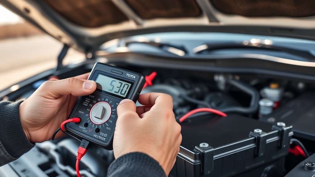
Set your multimeter to DC Volts (&Vmacr;) on the 20V scale (or Auto-Range). Place the red multimeter probe firmly on the clean positive (+) lead battery post and the black probe on the negative (−) battery post.
- 12.60V to 12.68V: 100% Fully charged.
- 12.40V to 12.45V: ~75% Charged; acceptable for testing.
- 12.20V: ~50% Discharged.
- Below 12.00V: Deeply discharged. Stop and fully recharge the battery with an external charger before testing the alternator. A deeply depleted battery draws excessive current, artificially pulling down running voltage and causing misleading test results.
Step 2: Start the Engine and Read Charging Voltage
Start the engine and let it settle into a smooth idle. Keep your multimeter connected directly across the battery posts and observe the display.
On standard Tacoma systems, voltage should immediately climb above resting voltage to a steady 13.7V to 14.7V DC. Under general DENSO factory testing standards, output measured at ~2,000 RPM should stay between 13.0V and 15.0V DC.
3rd & 4th Gen Smart Charging Override: If your 2016–2026 Tacoma battery is fully charged, the ECM may intentionally command the alternator down to ~12.8V–13.2V at idle to conserve fuel. To force the alternator into high-output mode, turn on the high-beam headlights and switch the HVAC blower motor to high. Voltage should quickly jump above 14.0V.
| Multimeter Reading | Diagnostic Meaning | Required Next Step |
|---|---|---|
| ~12.6V (Engine Off) | Battery resting state is healthy | Start engine for charging output test |
| 13.7V to 14.7V (Idle / Loaded) | Optimal charging performance | Proceed to electrical load and ripple tests |
| 13.0V to 15.0V (@ 2,000 RPM) | Within DENSO baseline specification | Verify positive/negative side voltage drop |
| Stays near ~12.4V–12.6V (No Rise) | No alternator output (Undercharging) | Inspect ALT fuse, ALT-S fuse, drive belt, wiring, and grounds |
| Above 15.2V (Sustained) | Overcharging (Regulator/Sense fault) | Check 7.5A ALT-S fuse; replace internal voltage regulator/alternator |
Step 3: Add Electrical Load at 2,000 RPM
To verify the alternator’s capacity to deliver required amperage under heavy demand, introduce high-draw accessories: turn on high-beam headlights, fog lights, front/rear defrosters, and set the HVAC blower to maximum speed. With an assistant holding engine speed steady at roughly 2,000 RPM, record the voltage across the battery posts.
- Pass: Voltage remains stable between 13.5V and 14.5V DC. A momentary dip followed by recovery confirms the internal regulator is adjusting field current properly.
- Fail: Voltage steadily drops down toward resting battery voltage (below 12.8V DC) and fails to recover. This indicates worn alternator brushes, a faulty internal regulator, a slipping belt, or high circuit resistance.
How Do You Interpret Tacoma Charging-Voltage Readings?
Accurate diagnosis requires analyzing the complete charging profile rather than relying on a single isolated number. Compare resting voltage against idle, loaded 2,000 RPM output, AC ripple, and voltage drops.
“A charging-system failure is not automatically an alternator failure. Battery sulfation, corroded ground cables, blown sensing fuses, and belt tensioners can all produce out-of-spec voltage readings at the battery.”
| Diagnostic Voltage Pattern | Root Cause Direction | Primary Action |
|---|---|---|
| Low resting (<12.2V), normal loaded output (>14.0V) | Discharged/failing battery or key-off drain | Conductance test battery; test for parasitic battery drain |
| Normal resting (12.6V), running stays at 12.6V | Zero charging output or open circuit | Inspect ALT fusible link (120A/140A), ALT-S fuse, and alternator plug |
| Passes at idle (14.2V), collapses under load (<12.8V) | Weak alternator field/brushes, belt slip, or circuit resistance | Perform voltage drop tests and inspect belt tensioner |
| Running voltage exceeds 15.2V consistently | Faulty internal regulator or blown ALT-S sense line | Check 7.5A ALT-S fuse in engine bay; replace regulator |
| Normal DC voltage, AC ripple exceeds 0.10V AC | Blown or leaking rectifier diode | Confirm with lab scope; replace alternator rectifier |
| Voltage drop exceeds 0.20V on positive or negative side | Corroded cable, bad terminal crimp, or weak chassis ground | Clean and tighten cable connections or replace ground strap |
How Do You Test a Tacoma Alternator for AC Ripple?
An automotive alternator produces three-phase alternating current (AC) internally, utilizing an internal bridge rectifier containing six to eight silicon diodes to convert the output into direct current (DC). If one or more rectifier diodes fail open or short, pulsating AC voltage leaks into the vehicle’s electrical system.
Symptoms of excessive AC ripple include noticeable headlight or dashboard illumination flickering, high-pitched whining noise through the stereo speakers, erratic sensor readings, unexpected dashboard warning lights, and accelerated battery degradation. Review our Tacoma dashboard warning lights guide to differentiate charging system alerts from traction or powertrain trouble codes.
Testing AC Ripple Step-by-Step
- Start the engine, hold engine speed at ~1,500–2,000 RPM, and switch on the headlights and blower fan.
- Switch the digital multimeter dial to AC Volts (V~) or millivolts AC.
- Connect the red multimeter lead to the battery positive (+) post and the black lead to the battery negative (−) post.
- Observe the reading. Because the meter blocks DC voltage in this mode, it measures only the raw AC voltage ripple riding on top of the DC charging current.
According to Fluke alternator ripple testing guidance, baseline values are interpreted as follows:
| AC Voltage Ripple Reading | System Condition | Action Required |
|---|---|---|
| ≤ 0.05V AC (50 mV) | Healthy Rectifier Bridge | Normal operation; diodes functioning properly |
| 0.05V to 0.10V AC (50–100 mV) | Marginal / Caution | Inspect alternator grounds; retest under maximum electrical load |
| ≥ 0.10V to 0.30V+ AC (>100 mV) | Failed Rectifier Diode(s) | Confirm with shop oscilloscope; replace alternator / rectifier |
What Common Problems Can Mimic a Bad Alternator?
Before spending money on a replacement alternator, rule out external component failures that produce identical symptoms:
- Blown Master ALT Fusible Link (120A/140A): Located inside the main engine fuse box. If blown, the battery receives zero charge from the alternator despite the alternator spinning normally.
- Blown 7.5A ALT-S Fuse: The voltage sensing fuse in the engine fuse box. If blown, the regulator cannot monitor battery state, causing severe overcharging or no output.
- Corroded Battery Posts & Clamps: High contact resistance prevents charging current from flowing into the battery plates.
- Slipping or Worn Serpentine Belt / Tensioner: If the belt slips under load, the alternator rotor will not achieve the RPM necessary to produce rated current.
- Corroded Engine & Chassis Ground Straps: Check the main battery ground wire to the inner fender apron and the engine block ground strap (located near the starter/motor mount area on Tacoma 4.0L and 3.5L engines).
- Mechanical Bearing Failure: High-pitched whining or metallic grinding sounds from the front of the engine indicate worn rotor bearings or a seized decoupler pulley, rather than an electrical fault.
Which Follow-Up Tests Confirm a Tacoma Charging Fault?
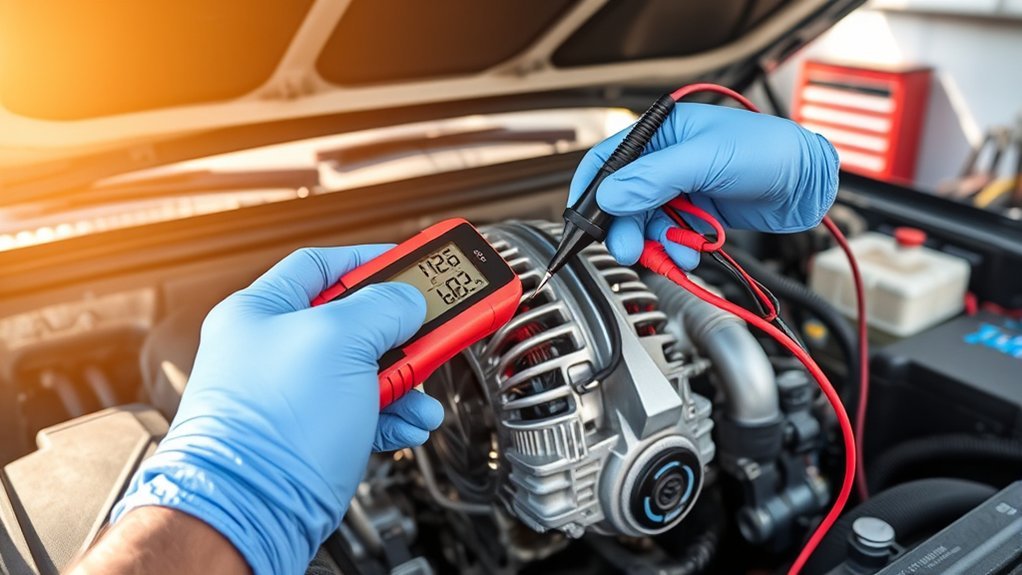
If overall voltage measurements remain inconclusive, perform voltage-drop testing to isolate resistance within the charging cables and connections.
Technician Safety Rule: The alternator B+ output stud carries unfused live battery power. Never let your metal multimeter probe touch the alternator housing while contacting the B+ stud, as this creates a direct short to ground. Attach insulated alligator clip leads with the engine turned OFF before starting the vehicle.
[Products Worth Considering]

This compact relay tester quickly checks the condition of most common 12-volt 4- and 5-pin automotive relays outside the vehicle. It provides self-contained testing without needing to connect to the battery, helping you identify coil and contact issues fast. Clear green and red LED indicators make pass or fail results easy to read, and the included batteries let you start using it right away.

This A-Premium serpentine belt is engineered for select Toyota, Scion, and Pontiac vehicles with the L4 2.4L gas engine, delivering dependable air conditioning drive performance. Made with durable EPDM and precision dimensions, it helps resist cracking, reduce noise, and maintain stable tension for smooth operation. It's designed for straightforward installation and backed by a one-year unlimited-mileage guarantee for added confidence.
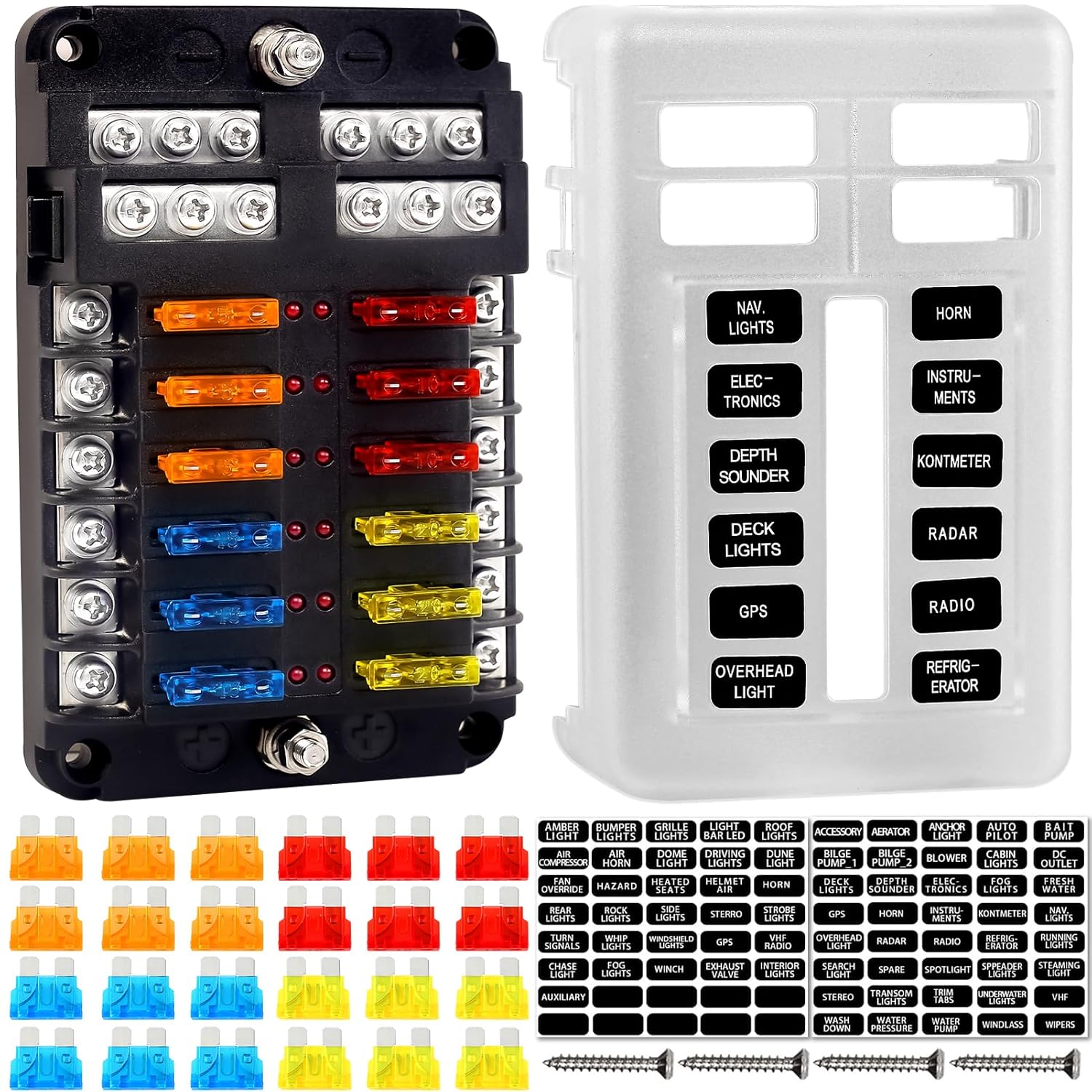
This 12-circuit fuse block provides organized, independent protection for vehicle and marine electrical systems, helping keep wiring neat and easier to maintain. Built with flame-retardant materials, nickel-plated copper components, and a protective cover, it offers reliable conductivity, corrosion resistance, and splash protection. LED indicators quickly identify blown fuses, while the included labels and extra blade inserts simplify installation and future service.
Positive-Side Voltage Drop Test
- Set multimeter to DC Volts (2V or low range).
- Attach the positive (red) meter probe directly to the threaded metal B+ output stud on the back of the alternator (pull back the rubber boot).
- Attach the negative (black) meter probe directly to the positive (+) lead post of the battery.
- Start the engine, turn on high beams and HVAC blower, and hold engine speed at 2,000 RPM.
- Interpretation: DENSO specifications require a voltage drop of 0.20V DC or less. A reading above 0.20V indicates excessive resistance in the main alternator charge cable, fusible link block, or positive terminal clamp.
Negative-Side Ground Voltage Drop Test
- Set multimeter to DC Volts (2V range).
- Attach the negative (black) meter probe to the clean unpainted aluminum case of the alternator.
- Attach the positive (red) meter probe directly to the negative (−) lead post of the battery.
- With the engine running at 2,000 RPM under load, observe the meter.
- Interpretation: Voltage drop should be 0.20V DC or less. A reading above 0.20V confirms high resistance in the engine-to-chassis ground strap, battery ground cable, or mounting bracket bolts.
Warning: Never perform the outdated “battery disconnect test” (unhooking a battery cable while the engine is running). On modern computerized Tacomas, disconnecting the battery eliminates the system’s primary voltage filter, generating inductive load-dump voltage spikes exceeding 60–100V that can instantly destroy the ECM, body control modules, and audio/navigation units.
When Should You Replace the Tacoma Alternator?
Replace the alternator only when repeatable testing confirms internal mechanical or electrical failure and all external variables (battery health, belt tension, fusible links, wiring grounds) have been verified as good:
- Running voltage remains below 13.0V at 2,000 RPM despite clean connections, good belt tension, and an intact ALT-S fuse.
- Regulated charging voltage continuously exceeds 15.2V DC under operating conditions, risking battery damage.
- AC ripple consistently measures above 0.10V–0.30V AC under load, confirming blown internal rectifier diodes.
- The alternator exhibits mechanical rotor bearing squeal, grinding, or a seized decoupler pulley.
- A professional bench test at an auto parts store verifies low amperage output or open stator windings.
If the red battery warning icon illuminates on your instrument cluster while driving, reduce electrical loads immediately and pull over in a safe area. According to Toyota Owners warning light documentation, a red charging alert indicates the vehicle is running solely on residual battery reserve and will lose power steering, ignition, and fuel pump operation once battery voltage falls below critical thresholds.
How Do You Maintain the Tacoma Charging System?
Simple preventive habits keep the Tacoma charging system reliable and prevent premature alternator burnout:
- Annual Battery Health Checks: Test battery Cold Cranking Amps (CCA) before extreme summer heat or winter freezes.
- Terminal Maintenance: Coat cleaned battery posts and cable clamps with dielectric grease or anti-corrosion spray.
- Drive Belt Inspection: Check the serpentine belt for rib cracking, edge fraying, and tensioner alignment at every 10,000-mile service interval.
- Proper Aftermarket Load Wiring: When adding winches, high-output LED light bars, auxiliary refrigerators, or AC inverters, use proper gauge wiring, dedicated relays, and appropriate inline fuses. Consider upgrading to a high-output 130A factory towing package alternator or AGM dual-battery setup if running heavy overland loads.
- Address Parasitic Drains Promptly: If your battery repeatedly loses charge overnight while the alternator tests normal, perform a dedicated parasitic battery drain test across the fuse panel.
Does the Tacoma i-FORCE MAX Hybrid Use the Same Alternator Test?
No. The 4th Generation (2024–2026+) Tacoma i-FORCE MAX hybrid does not use a conventional mechanical belt-driven alternator. Instead, it utilizes an electric motor-generator (MG) integrated inside the transmission bellhousing and a solid-state bidirectional DC-DC converter that steps down high voltage from the 288V hybrid traction battery pack to 12V–14V to operate standard vehicle accessories and recharge the auxiliary 12V battery.
Per Toyota 2025 Tacoma Hybrid safety guidance, DIY diagnostics on i-FORCE MAX models must be strictly limited to measuring resting and operating voltage across the accessible 12V auxiliary battery posts. Never touch, probe, or cut into orange high-voltage cables or open hybrid power converter covers. If an i-FORCE MAX exhibits charging system malfunctions or hybrid dashboard warnings, consult a certified Toyota hybrid technician.
Frequently Asked Questions
How do I know if my Toyota Tacoma alternator is bad?
Key indicators include the dashboard battery warning light, dim or flickering headlights, repeated dead battery episodes, electrical accessory failure while driving, bearing whining noises, and multimeter readings that stay below 13.0V DC or exceed 15.2V DC while the engine is running under load. Always inspect the ALT fusible link, belt tension, and battery health before replacing the unit.
What should a Tacoma alternator read on a multimeter?
A fully charged battery reads ~12.6V DC with the engine off. Under normal running conditions, a Tacoma alternator should output 13.7V to 14.7V DC across the battery posts. DENSO specifies an acceptable output range of 13.0V to 15.0V at 2,000 RPM under load. On 3rd and 4th Gen models with smart charging, turn on high beams and HVAC blower to verify output above 14.0V.
Can a bad battery make a Tacoma alternator test look bad?
Yes. A sulfated, internally shorted, or severely discharged battery draws massive charging current from the alternator, dragging down system voltage readings and creating erratic results. Always recharge and conductance-test the battery before concluding the alternator is defective.
Can an alternator pass at idle and fail under load?
Yes. An alternator with worn carbon brushes, a failing diode, or a slipping serpentine belt may produce 14.0V DC at idle when electrical demand is low, but collapse below 12.8V DC when high-draw loads (headlights, defrosters, blower fan) are activated. Always test output at 2,000 RPM under maximum electrical load.
Why does my battery keep dying if the alternator voltage tests normal?
If alternator charging output is between 13.7V and 14.7V DC but the battery discharges overnight, the issue is typically a degraded battery that cannot hold a reserve charge, high contact resistance from corroded terminals, or an ongoing parasitic key-off drain pulling more than 50mA.
Is it safe to disconnect the battery cable while the Tacoma is running?
No. Disconnecting a battery cable while the engine is running causes a dangerous inductive load dump, creating rapid voltage spikes exceeding 60–100V. This can permanently destroy the engine control module (ECM), transmission control module, sensors, and multimedia units.
What does high AC ripple voltage mean?
High AC ripple (exceeding 0.05V to 0.10V AC) indicates that one or more internal silicon rectifier diodes have failed, allowing raw alternating current into the vehicle’s DC electrical system. This causes headlight flickering, stereo whine, sensor errors, and battery damage.
Does a Tacoma hybrid use the same alternator test?
No. The Tacoma i-FORCE MAX hybrid does not have a conventional mechanical alternator; it uses a high-voltage DC-DC converter powered by the hybrid battery pack. DIY testing is limited strictly to checking 12V auxiliary battery terminal voltage. Never touch or probe orange high-voltage cables.
Conclusion
To accurately test a Toyota Tacoma alternator with a multimeter, always begin with a fully charged battery, verify resting DC voltage, observe running voltage at idle and under electrical load at 2,000 RPM, and measure both voltage drop and AC ripple. On 3rd and 4th Gen models, remember to activate electrical accessories to account for ECM smart charging logic.
Before replacing an alternator, confirm that the serpentine belt, battery posts, 120A/140A ALT fusible link, 7.5A ALT-S fuse, and engine ground straps are in good condition. If sustained voltage exceeds 15.2V, output collapses under load, or AC ripple exceeds 0.10V AC, replacing the alternator or internal rectifier will restore complete charging system reliability.
Sources
- Fluke: How to Measure Battery Voltage with a Multimeter — Reference for battery resting potential and automotive alternator charging thresholds.
- Fluke: How to Test Alternator Ripple Voltage with a Multimeter — Authoritative baseline standards for multimeter AC ripple and diode diagnosis.
- DENSO Auto Parts: Charging System Troubleshooting — OEM alternator specifications, 2,000 RPM loaded output limits, and ≤0.2V voltage-drop testing guidelines.
- Toyota Owners: Dashboard Warning Lights — Safety protocols and operational limits for red instrument cluster charging system alerts.
- Toyota Owners: 2025 Tacoma Hybrid 12-Volt Battery Safety — Official manufacturer documentation regarding i-FORCE MAX 12V auxiliary battery service and high-voltage hybrid safety protocols.



[…] Tacoma parasitic battery drain guide for key-off draw diagnosis. For a conventional gas Tacoma, the Tacoma alternator multimeter guide explains a basic charging […]