

Toyota Tundra ABS and Traction-Control Light Reset: Quick Diagnosis Path
If your Toyota Tundra ABS and traction-control lights stay on, do not clear them blindly. First check whether the red brake warning light is also on, confirm the brake lights work, and save any ABS, VSC, TRAC, 4WD, and engine codes if you have a compatible scanner. A battery reset may clear a temporary warning after the fault is fixed, but it can also erase the diagnostic clues that tell you which circuit failed.
Quick Answer
To reset Toyota Tundra ABS and traction-control lights safely, scan and record codes first if possible, inspect brake fluid and brake-light operation, then try a power reset only if the truck brakes normally and the red brake warning light is off. Disconnect the negative battery terminal for 30 minutes, reconnect it, turn the steering wheel fully left and right twice, then drive slowly in a safe area. If the lights return, use a scan tool that reads Toyota ABS data before replacing parts.
Key Takeaways
- Do not use a reset as the first diagnostic step if you can scan codes, because clearing data can hide the real fault.
- Check brake fluid, brake-light operation, stop-lamp fuse power, and the brake-light switch before buying ABS parts.
- Use an enhanced scanner because many basic OBD2 readers miss chassis, ABS, VSC, TRAC, and 4WD module data.
- Treat Toyota C1201/51 as an engine-control malfunction signal first, then repair the primary engine code before chasing ABS parts.
- Stop driving when the red brake warning light appears, brake fluid looks low, the pedal feels soft, or the truck shows poor braking.
What’s in This Article
- Reset or Diagnose First?
- Before You Begin
- Battery Reset and Steering Recalibration
- Test the Brake-Light Switch at the Pedal
- How to Test Stop-Lamp Fuse Power, Relays, and Wiring
- When to Use a Scan Tool and Which ABS/Traction Codes to Read
- Test Wheel-Speed Sensors and Wheel Harnesses
- Diagnose ABS Module and Steering-Angle Sensor Faults
- Common Mistakes That Keep the Lights On
- Cost-Effective Fixes vs. Professional Repair
Reset or Diagnose First?
A reset makes sense only after you rule out obvious brake and electrical problems. ABS is a closed-loop brake-control system that monitors wheel rotation and warns the driver when the system detects a malfunction, according to NHTSA. Stability control also builds on ABS and can use wheel-speed and steering inputs to help maintain control on curves and slippery roads.
| Light Pattern | What to Do First | Why It Matters |
|---|---|---|
| ABS light only | Scan and save ABS codes, then check fuses and wheel wiring. | Normal braking may remain, but anti-lock braking may be disabled. |
| ABS plus red BRAKE warning | Stop, check fluid level, and look for leaks or a soft pedal. | This can point to a hydraulic brake problem, not just an ABS fault. |
| ABS, TRAC/VSC, and check-engine light | Scan engine codes first and treat C1201 as secondary until proven otherwise. | Toyota C1201/51 can set when the skid-control ECU receives an engine-control malfunction signal. |
| ABS/TRAC plus flashing 4HI or 4LO | Scan ABS and 4WD modules before cycling parts. See the Tundra 4LO light guide if 4WD warnings appear. | A chassis fault can affect traction, stability, and 4WD logic at the same time. |
Before You Begin
Estimated total time: 45 to 90 minutes for basic checks, plus more time if you need sensor testing or wiring repair.
You need basic hand tools, safety glasses, a multimeter, electrical contact cleaner, a helper, and a scan tool that can read Toyota ABS data. Park the truck on level ground, set the parking brake, and keep the wheels chocked during electrical checks.
- Use jack stands any time you lift the truck.
- Save radio presets or memory settings before you disconnect the battery.
- Record every diagnostic trouble code before you clear anything.
- Check your owner’s manual or Toyota service data for fuse names on your exact model year.
- [VERIFY: Confirm the exact steering-angle zero-point calibration procedure for the specific Tundra model year before publishing service-procedure language.]
Battery Reset and Steering Recalibration
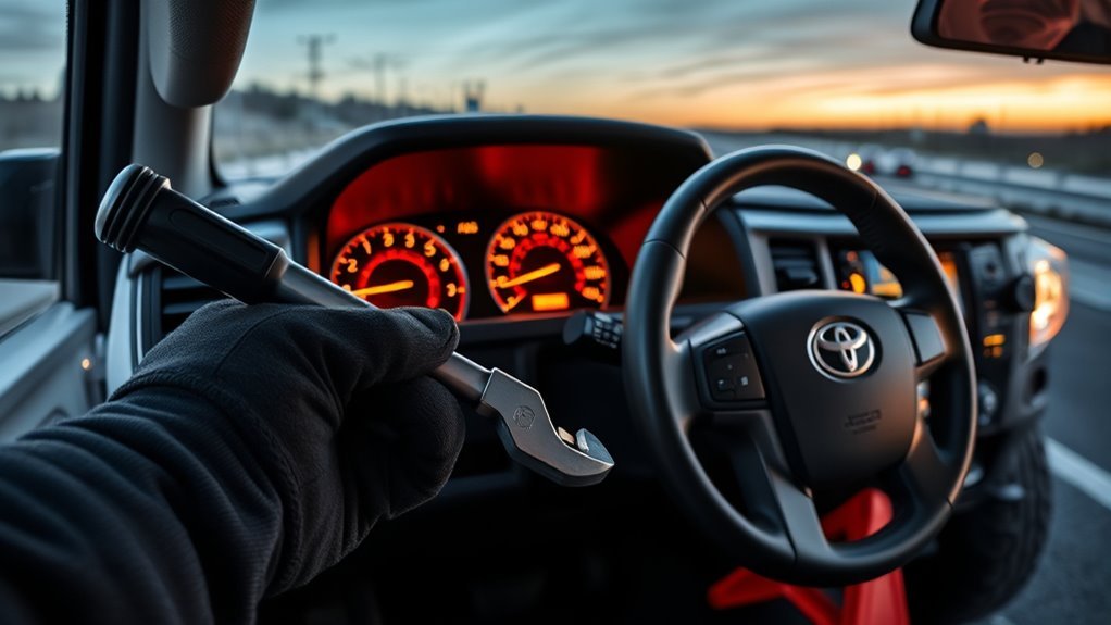
A battery reset removes power from control modules. It can clear a soft fault after you fix the cause, but it will not repair a bad sensor, an open circuit, low brake fluid, or an ABS control problem.
Follow these steps only after the truck passes the brake-fluid and brake-light checks:
- Park safely and turn the ignition off. Set the parking brake, remove the key, and keep all accessories off.
- Record codes first if you can. Save stored, pending, history, and freeze-frame data before you disconnect power.
- Disconnect the negative battery terminal. Leave it off for at least 30 minutes so the modules power down.
- Reconnect the terminal and turn the ignition on. Do not start the engine yet.
- Turn the steering wheel fully left, then fully right, twice. This may help some systems recognize steering range, but a true steering-angle zero-point calibration can require Toyota service software or an enhanced scan tool.
- Start the engine and drive slowly for about two minutes. Watch the dashboard. If the warning lights turn off and stay off, you likely cleared a temporary stored fault.
- Confirm the brake lights work again. Ask someone to watch the rear lights while you press the pedal.
If the lights come back on during or after the drive, the truck still has a hardware, wiring, calibration, or control-module fault. Plug in a Toyota-compatible scan tool, read the codes, and continue with the next checks.
Warning: Stop driving if the regular brake warning light also comes on because low brake fluid or a brake fault can reduce braking performance.
Test the Brake-Light Switch at the Pedal
The brake-light switch sits near the top of the brake pedal arm, close to the firewall. A bad switch can trigger ABS and traction-control warnings, disable the shift lock, and stop the brake lights from working.
Locate the Brake Switch
Inspect the brake-light switch mounted near the pedal. Look for a small plastic unit with a plunger that the pedal arm moves when you press and release the pedal.
Confirm the connector seats firmly and the harness has no cuts, rub marks, or loose pins. If the connector feels loose, secure it before you test the switch.
Inspect for Debris
After you find the switch, inspect the switch body and nearby bracket for debris or corrosion. Dirt can block the plunger, and corrosion can weaken the electrical signal.
Use contact cleaner, a soft brush, and compressed air. Don’t use sharp tools because they can damage the switch housing or wiring.
| Item Inspected | Action |
|---|---|
| Plunger | Brush, air, cycle pedal |
| Contacts | Spray contact cleaner, dry thoroughly |
| Wiring harness | Check for breaks and secure connectors |
If cleaning doesn’t restore normal signals, move on to electrical testing.
Test Switch Operation
Have an assistant press the brake pedal while you watch the rear brake lights. No brake lights often point to a bad switch, blown fuse, missing power, or damaged wiring.
Set a multimeter to continuity or ohms, then probe the switch terminals while you press and release the pedal. Most circuits show continuity when you press the pedal, but you should confirm the correct test method for your model year.
Adjust the switch so the plunger fully moves with the pedal. If cleaning and adjustment don’t restore function, replace the switch and test the lights again. RepairPal’s 2026 estimate lists a 2025 Tundra brake-light switch replacement at $139 to $179 before taxes, fees, and location differences, making it far cheaper than ABS module work.
How to Test Stop-Lamp Fuse Power, Relays, and Wiring
Check stop-lamp fuse power, relay operation, and related wiring before you move to sensor or module testing. Use the fuse diagram for your exact Tundra, then check the stop-lamp fuse and ECU ignition feed with a voltmeter or test light.
With the ignition on and the brake pedal pressed, you should see battery voltage on the correct side of the stop-lamp circuit. If the fuse tests good, confirm the brake-light relay clicks during activation and inspect the brake-switch connector for corrosion, missing voltage, or damaged pins.
Stop-Lamp Fuse Power
The stop-lamp circuit feeds more than the rear lamps on many vehicles, so start here. A single blown fuse or open feed can disable brake lights and upset ABS or traction-control logic at the same time.
- Measure voltage at the stop-lamp fuse during pedal activation.
- Test continuity between the fuse, brake-light switch, and related connector.
- Inspect the ECU ignition feed fuse listed for your model year.
- Find the short before you replace any fuse that blows again.
Relay and Wiring Checks
Confirm switched battery voltage at the stop-lamp fuse terminal when your assistant presses the pedal. No voltage at that point usually means the fault sits upstream of the fuse.
Run relay diagnostics next. Ask your assistant to press the pedal while you listen for the brake-light relay click. Probe the coil and contact terminals for voltage and continuity. Replace the relay if it doesn’t click or fails a continuity test during activation.
Inspect the wiring from the fuse to the brake-light switch and rear lamps. Look for chafing, breaks, corrosion, or loose connectors. Note any recent electrical changes because aftermarket accessories often create brake-circuit faults.
When to Use a Scan Tool and Which ABS/Traction Codes to Read
If ABS or traction-control lights stay on after basic checks, use a scan tool to pull stored, pending, and history codes. A code-first diagnosis helps you target the actual fault instead of replacing parts that still work.
Use a scan tool when:
- Warning lights remain after relay and wiring checks pass.
- Intermittent faults appear, or codes return after clearing.
- You need live wheel-speed and ABS module data to confirm a symptom.
- You want to verify the repair before you drive the truck normally.
Start with ABS codes that identify wheel-speed circuits, steering-angle data, brake-light input, voltage supply, brake-fluid level, or module communication. Some code numbers vary by year and scan-tool database, so record the full code and description exactly as shown.
Pay close attention to C1201 on Toyota vehicles. Toyota service information describes C1201/51 as an engine-control system malfunction signal received by the skid-control ECU. Check and repair the primary engine code first, then clear and retest the ABS, VSC, and traction-control system.
Also take the red brake warning light seriously. Toyota service information for C1202/52 and C1202/58 ties brake-fluid level or the brake-fluid level warning-switch circuit to warning-light behavior. Do not keep driving if fluid is low or the pedal feels wrong.
Pro tip: Use Toyota Techstream or a compatible enhanced scanner so you can view live wheel-speed data for each sensor.
[Products Worth Considering]

The FOXWELL NT301 is a plug-and-play OBD2 code reader designed to help drivers and home mechanics diagnose check engine light issues with ease. It reads fault codes, clears emissions-related warnings, displays live sensor data in graph form, and shows I/M readiness so you can quickly check vehicle status before an emissions test. With broad compatibility across many OBD2 vehicles and a clear color screen, it offers a practical, user-friendly way to monitor and troubleshoot engine performance.

This automotive test light combines a bright LED voltage display with quick polarity indication for fast, accurate circuit checks in a wide range of vehicle systems. It helps diagnose battery, charging, lighting, and fuse issues with a sharp stainless probe, long spring wire, and easy-to-use alligator clip for efficient troubleshooting.

This Yuirote universal car motor diagnostic tool helps drivers quickly detect engine fault codes and identify system issues for routine inspections and maintenance. It also supports electronic parking brake reset and emergency release functions, making it useful for handling EPB-related problems without a repair shop visit. Its compact, ergonomic design and broad vehicle compatibility make it a practical choice for car owners and DIY repair enthusiasts.
Test Wheel-Speed Sensors and Wheel Harnesses
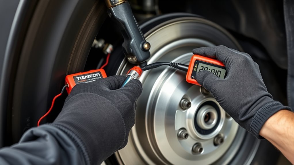
Check the wheel-speed sensors and harnesses when codes or live data point to one corner. Lift the wheel, support the truck on jack stands, and trace the wiring from the sensor to its connector.
Look for chafing, fraying, corrosion, broken wires, and loose pins that can cause intermittent data loss. Clean corroded connectors, reseat them, and repair any damaged wiring sections before you replace the sensor.
Note: Many later-model Toyota wheel-speed sensors use active electronics, so live data and signal testing often give you better answers than resistance checks alone.
If a sensor produces no output or an erratic signal, replace it with a quality part that matches your exact model year. RepairPal’s 2026 Tundra wheel-speed sensor estimate ranges from $323 to $492 before taxes, fees, and location differences. Re-test after replacement, clear the codes, and confirm the warning lights stay off after a short drive.
[Products Worth Considering]

The ZMOON ZM201 is a plug-and-play OBD2 code reader designed to quickly diagnose check engine issues on compatible vehicles after 1996. It reads and clears engine fault codes, displays live data and freeze frame information, checks I/M readiness, and helps you identify problems before visiting a repair shop. With a color screen, intuitive controls, and built-in DTC database, it offers an easy-to-use solution for DIY drivers and car owners who want reliable engine diagnostics.

The TOPDON VeriDiag X800 BT is a wireless bidirectional automotive diagnostic scanner designed for full-system troubleshooting, active testing, and advanced service resets. It supports broad vehicle coverage, live data viewing, AutoVIN identification, and lifetime free updates to help DIYers and professionals diagnose issues faster and with greater confidence.
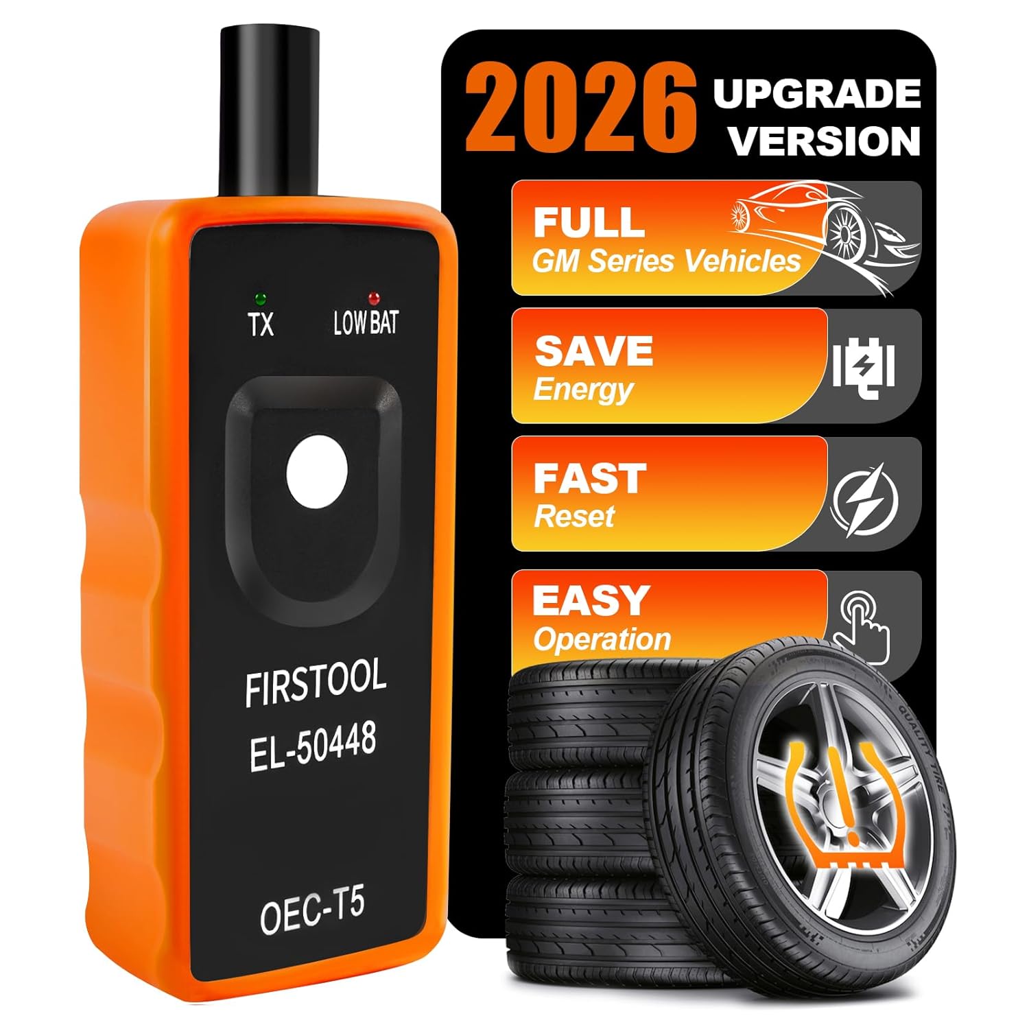
This EL-50448 TPMS relearn tool helps quickly activate and reset tire pressure sensors so your vehicle’s monitoring system stays accurate after tire rotations, sensor replacement, or seasonal tire changes. Designed for many GM-related vehicles and compatible with common 315 and 433 MHz TPMS systems, it offers simple one-button operation and reliable performance for clearing warning lights and relearning sensor positions.
Diagnose ABS Module and Steering-Angle Sensor Faults
The ABS module and steering-angle sensor help the truck compare wheel speed, brake input, and steering input. Read diagnostic trouble codes and live data before you blame either part.
Use a scan tool that reads ABS-specific codes and streams wheel-speed and steering-angle values. Turn the wheel through its full range and watch whether the steering-angle value changes smoothly.
Inspect connectors and wiring for corrosion, breaks, or loose pins. These faults often show up as intermittent signals in live data instead of steady failures.
- Read ABS module codes and record live wheel-speed traces per corner.
- Verify steering-angle sensor output during lock-to-lock rotation.
- Inspect harnesses and grounds for damage or high resistance.
- Run sensor calibration through Toyota service software when the procedure calls for it.
Do not approve an ABS control-module replacement based on dashboard lights alone. RepairPal’s 2026 Tundra ABS control-module estimate is $4,700 to $4,791 before taxes, fees, and location differences, so you want code, power, ground, and live-data proof before paying for that repair.
Common Mistakes That Keep the Lights On
Many Tundra owners clear codes too early, then lose the data that points to the real fault. Record every code, freeze-frame detail, and live-data symptom before you reset the system.
- Don’t replace the ABS module before you check fuses, grounds, and brake-light input.
- Don’t ignore engine codes when C1201 appears with traction-control lights.
- Don’t use only a generic OBD2 scanner if you need Toyota ABS live data.
- Don’t assume the steering-angle sensor is recalibrated just because you turned the wheel lock to lock.
- Don’t test a lifted truck unless jack stands support it securely.
Cost-Effective Fixes vs. Professional Repair: Parts, Labor, and Next Steps
Once you isolate the fault area, compare DIY checks against professional service. Basic electrical checks cost little, but ABS module work can become expensive fast.
- DIY minor fixes: Test the brake-light switch, clean connectors, check fuses, and inspect wiring before you authorize shop labor.
- Tool-assisted DIY: Buy or borrow a scan tool that reads Toyota ABS data, then verify codes and live data before you replace sensors.
- Professional service: Get a written quote when testing points to the ABS module, internal hydraulic unit, or steering-angle calibration.
Tackle the brake-light switch, fuses, and wiring before you approve major ABS work. These checks can save money and help you explain the fault clearly to a mechanic.
If warning lights persist after those checks, professional diagnosis helps prevent a small electrical fault from turning into a larger repair bill.
[Products Worth Considering]
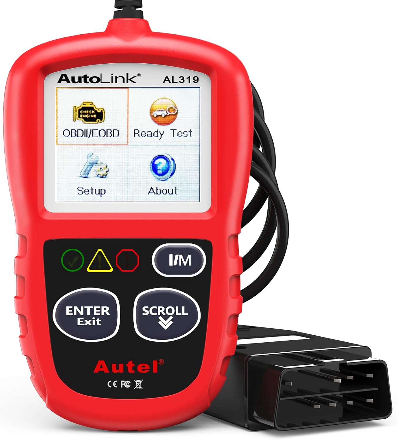
The Autel AL319 is a user-friendly OBD2 scan tool designed to help drivers quickly diagnose check engine light issues and understand vehicle fault codes. It supports reading and clearing DTCs, live data, freeze frame, I/M readiness, and vehicle information, making it a practical choice for DIYers and everyday car owners. With plug-and-play operation, a color display, built-in speaker, and broad vehicle compatibility, it delivers fast, reliable diagnostics without complicated setup.

BlueDriver Pro turns your phone or tablet into a powerful vehicle diagnostic scanner with wireless Bluetooth connectivity and no subscription fees. It reads and clears enhanced trouble codes for systems like ABS, SRS, Airbag, TPMS, and Transmission, while also providing technician-verified repair reports, live data, freeze frame views, smog readiness checks, and Mode 6 test results. Built for broad coverage on gas vehicles sold in North America, it offers professional-grade diagnostics with easy setup and 24/7 North American support.

The ANCEL AD310 is a compact, easy-to-use OBD II code reader designed to help drivers quickly identify check engine light causes, read and clear fault codes, and review key vehicle data. It supports major OBD2 protocols and works with many 1996-and-newer cars, light trucks, SUVs, and other OBD2 vehicles. Built for fast diagnostics at home or on the go, it runs directly from the vehicle and provides clear results on a large screen.
Frequently Asked Questions
Why is my traction-control light staying on my Toyota Tundra?
The most common causes include a brake-light switch fault, a wheel-speed sensor issue, a blown fuse, damaged wiring, a low brake-fluid warning, or a steering-angle sensor that needs calibration. Use a scan tool to pull ABS and engine codes before you replace parts.
Is it safe to drive a Toyota Tundra with the ABS light on?
You may still have normal braking if only the ABS light stays on, but the anti-lock function may not work during hard braking. Stop driving and inspect the brake system right away if the regular brake warning light also comes on, fluid is low, or the brake pedal feels soft.
How do I know if my wheel-speed sensor is bad on a Toyota Tundra?
A bad wheel-speed sensor may trigger a wheel-speed circuit code and show erratic live data at one wheel. Check the harness and connector first, then test the signal while you rotate the wheel by hand.
What does fault code C1201 mean on a Toyota Tundra?
On Toyota systems, C1201/51 usually means the skid-control ECU received an engine-control malfunction signal. Check the engine control module codes first, repair the primary engine fault, then clear and retest the ABS and traction-control system.
Can I reset the ABS light on a Toyota Tundra without a scan tool?
You can disconnect the negative battery terminal for 30 minutes to clear some stored faults temporarily. If the underlying fault remains, the light will return, and a scan tool will help you confirm the cause.
Why are my ABS, traction-control, and check-engine lights on together?
Those lights can appear together when the truck disables traction or stability functions after an engine-control, brake-input, wheel-speed, or module-communication fault. Scan both engine and ABS modules before replacing sensors.
Safety Disclaimer: This article is for informational purposes only and does not replace professional automotive repair advice. ABS and traction-control systems affect braking and stability. If you’re unsure about any step or the warning lights persist, consult a qualified mechanic before you drive the vehicle.
Conclusion
Start with the simple checks because brake-light switch, fuse, connector, fluid-level, and reset issues often mimic larger ABS faults. Record the codes before you clear them, then test the system in a safe order.
If the lights return, use Toyota ABS live data to confirm the failed circuit before you buy parts. When the diagnosis points to the ABS module or steering-angle calibration, get a professional quote and share your scan-tool findings.
A careful diagnosis gives you the best chance to fix the warning lights without wasting money or ignoring a real brake-system fault.
References
- Toyota Owner Resources — Toyota Motor Corporation
- Anti-Lock Braking System Definition and Warning-Light Requirements — National Highway Traffic Safety Administration
- Electronic Stability Control and ABS Relationship — Insurance Institute for Highway Safety
- Steering Angle Sensor Reset Guidance — Snap-on Diagnostics
- Diagnostic Trouble Code Definitions — SAE International
- 2025 Toyota Tundra Brake-Light Switch Replacement Cost — RepairPal, 2026
- Toyota Tundra Wheel-Speed Sensor Replacement Cost — RepairPal, 2026
- Toyota Tundra ABS Control Module Replacement Cost — RepairPal, 2026



[…] message remains, treat it as a diagnostic issue rather than a normal driver-selected mode. See the Toyota Tundra ABS and traction-control light diagnosis guide for the fault-focused […]