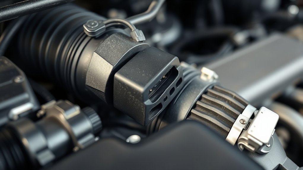
A faulty or contaminated Toyota Camry Mass Air Flow (MAF) sensor disrupts the engine control module’s (ECM) fuel calculations, leading to rough idle, hesitation under load, engine stalling, hard starting, poor fuel economy, or a check engine light. However, these drivability symptoms often mimic intake vacuum leaks, cracked PCV hoses, or weak fuel delivery. Before replacing the sensor, save all diagnostic trouble codes (DTCs) and freeze-frame data, inspect the air intake ducting and wiring harness, and verify live airflow (g/s) and fuel trims against factory specifications for your specific Camry engine.
By Auto Review Nest Editorial Team · Last updated: August 30, 2026
How this guide was prepared: This diagnostic guide synthesizes Toyota Technical Information System (TIS) workshop manuals, Toyota OEM parts technical documentation, and DENSO engine management engineering bulletins. It provides a standardized troubleshooting framework across 2.5L I4, 3.5L V6, and Hybrid Camry powertrains.
Model-Year & Engine Scope: Camry MAF sensor design, signal output (analog voltage vs. digital frequency), normal airflow ranges, and cleaning procedures vary across generations (XV40, XV50, XV70, XV80) and engine families (2.5L A25A-FKS/2AR-FE, 3.5L 2GR-FE/2GR-FKS, and Hybrid THS-II systems). Always match diagnostic steps to your vehicle’s exact engine code and VIN.
Quick Diagnostic Summary
- Common Fault Codes: P0101 (circuit range/performance), P0102 (circuit low input), P0103 (circuit high input), and P0171 (system too lean, bank 1).
- Normal Warm Idle Airflow (P/N, 650–750 RPM, Loads Off): 1.8–2.5 g/s for 2.5L 4-Cylinder engines; 2.6–3.7 g/s for 3.5L V6 engines.
- Dynamic WOT Rule: Peak airflow near redline should reach roughly 75% to 85% of rated engine horsepower in grams per second (g/s).
- Vacuum Leak vs. Bad MAF: Positive fuel trims that are high (+15% to +25%) at idle but normalize at 2,500 RPM indicate unmetered vacuum leaks, not a bad MAF sensor.
For foundational scanner setup, see our guide on how to read OBD-II codes on a Toyota Camry.
Key Diagnostic Takeaways
- Never replace a MAF sensor based solely on trouble codes or drivability symptoms without live scan-tool verification.
- Code P0171 indicates the ECM is compensating for a lean condition; this is frequently caused by intake boot tears or PCV leaks rather than sensor failure.
- Cleaning procedures differ by sensor generation: older hot-wire sensors tolerate dedicated MAF chemical spray, while modern digital slot-style sensors require controlled low-pressure air cleaning per Toyota service bulletins.
- Always inspect connector pin tension, +12V power supply, chassis ground, and the 5V reference circuit before condemning the sensor assembly.
Diagnostic Overview at a Glance
| Time Required | 20–45 minutes for scan-tool verification and intake inspection; 60+ minutes for circuit pinout testing |
| Difficulty Level | Beginner (data logging & visual check) to Intermediate (multimeter back-probing & smoke testing) |
| Essential Tools | OBD-II live data scanner (g/s and fuel trims), digital multimeter (DMM), Phillips screwdriver/socket set, flashlight, MAF cleaner / low-pressure air |
| Diagnostic Outcome | Identify unmetered intake leaks, repair harness/connector corrosion, safely clean contaminated sensing elements, or install a verified OEM replacement |
What Are the Symptoms of a Bad Toyota Camry MAF Sensor?
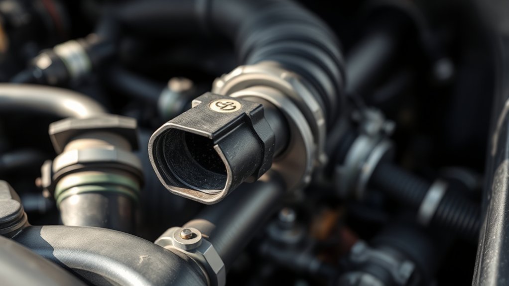
When a Camry MAF sensor fails or becomes coated with dirt, oil, or silica dust, it reports inaccurate air mass data to the ECM. Because the ECM uses this signal as the primary calculation for injector pulse width (fuel delivery), drivability issues emerge across specific operating states:
- At Idle: Erratic engine speed hunting (surging between 500 and 1,000 RPM), severe engine vibration, or sudden stalling immediately after starting or when stopping at red lights.
- Under Acceleration: Noticeable throttle lag, stumble or flat spots during tip-in, lack of high-RPM passing power, or engine transmission shift hesitation caused by mismatched calculated engine load tables.
- Fuel Economy & Emissions: Significant drop in miles per gallon (MPG), black exhaust soot (rich condition), or a pungent fuel smell caused by an over-reporting sensor over-fueling the combustion chambers.
- Warning Lights: Illumination of the Check Engine Light (CEL), often accompanied by TRAC OFF / VSC lights due to ECM torque calculation interlocks.
| Diagnostic Symptom / Code | Root Operational Cause | Initial Inspection Target |
|---|---|---|
| Rough Idle / Engine Stumble | Erratic air mass signal or unmetered air entering post-MAF | Intake accordion boot bellows, PCV breather hoses, air filter box latches |
| Hesitation Under Moderate Load | Contaminated sensing element under-reporting true air volume | Live scan data at 2,500 RPM, freeze-frame load calculation, sensing element cleanliness |
| DTC P0101 | MAF sensor performance/plausibility signal outside expected throttle-angle map | Intake restrictions, dirty throttle bore, unmetered air leaks, skewed sensor element |
| DTC P0102 / P0103 | Circuit low input (open/short to ground) or high input (short to power/open ground) | 5-pin connector lock tab, terminal back-out, +12V power supply, chassis ground circuit |
| DTC P0171 (System Lean) | Total fuel trim exceeds +20% to +35%; ECM adding fuel to correct excess oxygen | Intake manifold gaskets, PCV valve & hoses, fuel pump pressure, under-reading MAF |
Diagnostic Rule: Code P0171 does not indicate a bad MAF sensor by default. It confirms the ECM detected a lean exhaust condition via the Air-Fuel Ratio (A/F) sensor. You must evaluate fuel trim reaction at idle versus 2,500 RPM to isolate unmetered vacuum leaks from sensor error.
Can You Drive a Toyota Camry With a Bad MAF Sensor?
You should not drive a Camry exhibiting severe drivability symptoms such as engine cutting out, violent hesitation, sudden stalling in traffic, or a flashing Check Engine Light. A flashing CEL indicates active engine misfires capable of overheating and destroying the catalytic converter within minutes. If the car experiences severe stalling during deceleration or merging, it poses a direct safety hazard.
If the engine operates smoothly and the CEL remains steadily illuminated with an isolated P0101 code, you may drive the vehicle a short distance directly to a repair facility. Keep engine speeds moderate, avoid wide-open throttle acceleration, do not tow, and diagnose the system promptly to prevent excessive carbon accumulation or spark plug fouling from incorrect air-fuel ratios.
How Do the Camry MAF and IAT Sensors Work?
The Camry MAF sensor is located inline within the intake air tube between the engine air filter housing and the throttle body. Its core function is to measure the exact mass (weight) of air entering the cylinders, which accounts for ambient temperature and barometric pressure variations.
Most modern Toyota Camry models utilize a plug-in slot-type mass air flow meter manufactured by DENSO. Inside the bypass air sampling channel, two primary circuits operate:
- Mass Airflow Measurement: A heated platinum wire or micro-machined silicon bridge element is maintained at a precise constant temperature differential above incoming ambient air. As incoming air flows past the element, it cools it down. The internal control circuit increases electric current to maintain the target temperature. The current variation is converted into a calibrated output signal (an analog 0.5–4.5V signal on older systems, or a digital square-wave pulse frequency signal on newer TNGA/Dynamic Force architectures) sent directly to the ECM.
- Intake Air Temperature (IAT) Sensor: A negative temperature coefficient (NTC) thermistor exposed in the intake air stream measures incoming air temperature. As air temperature increases, electrical resistance decreases, allowing the ECM to adjust base timing and fine-tune density calculations.
For additional details on underlying sensor hardware, DENSO’s MAF technical overview outlines internal circuit operation and bypass channel architecture.
OEM Nomenclature: Toyota service literature and parts catalogs officially refer to this component as the “Meter Sub-Assy, Intake Air Flow” or “Air Flow Meter.” Ensure part orders match your Camry’s exact VIN, production date, and emissions specification (California CARB vs. Federal EPA).
How Does the Camry ECM Use MAF Data for Engine Management?
The ECM relies on the MAF signal as the primary load parameter across all closed-loop and open-loop operating conditions:
- Fuel Injection Duration: Calculates base injection duration (pulse width in milliseconds) to maintain the stoichiometric 14.7:1 air-fuel target for gasoline combustion.
- Ignition Timing Advance: Determines engine cylinder load to look up base spark advance angles from ignition timing maps, preventing detonation (engine knock).
- Transmission Shift Scheduling: The Transmission Control Module (TCM) utilizes calculated engine load from the MAF to manage shift points, line pressure, and torque converter lockup clutch engagement.
- Diagnostic Cross-Checks: The ECM continuously compares live MAF airflow against expected airflow models derived from Throttle Position (TPS), Manifold Absolute Pressure (MAP, where equipped), Engine Speed (RPM), and Variable Valve Timing (VVT) angles. A divergence triggers DTC P0101.
How Should You Diagnose Camry MAF Trouble Codes?
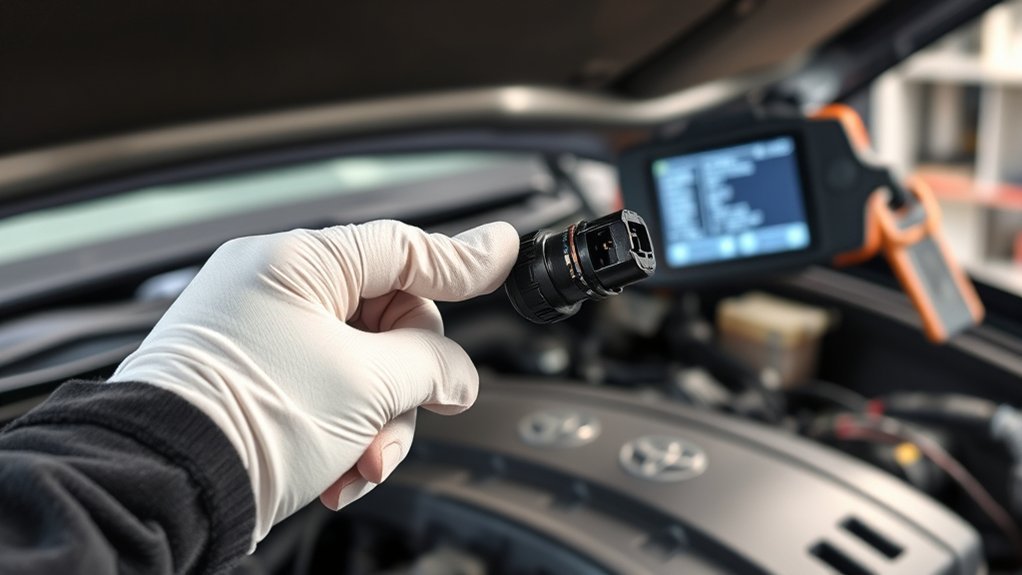
When troubleshooting diagnostic trouble codes P0101, P0102, P0103, or lean codes like P0171, follow a methodical, step-by-step diagnostic workflow before buying replacement parts:
- Capture Stored DTCs and Freeze-Frame Data: Record all active, pending, and permanent codes. Document engine RPM, Short Term Fuel Trim (STFT), Long Term Fuel Trim (LTFT), Coolant Temperature, and Vehicle Speed recorded at the exact moment the DTC set.
- Inspect Air Filter Box and Filter Element: Ensure the air filter is an approved OEM-spec paper element, clean, seated flat, and that the airbox latches are fully clamped. An oiled aftermarket filter can deposit oil film directly onto the heated sensing element.
- Check Intake Duct Sealing: Closely inspect the rubber/plastic intake boot between the MAF and the throttle body. Flex the accordion bellows by hand; fine cracks frequently open only under engine torque movement, admitting unmetered air.
- Inspect PCV and Vacuum Lines: Inspect PCV hoses, brake booster vacuum lines, and evaporative purge solenoid connections for splits, hardening, or loose clamps.
- Inspect Electrical Connector and Pins: Disconnect the MAF harness with ignition OFF. Inspect for green corrosion, backed-out female terminals, bent pins, or engine oil intrusion from leaking valve cover gaskets.
- Evaluate Live Data (Idle, 2,500 RPM, and WOT): Compare live airflow in grams per second (g/s) and fuel trim responses against factory engineering standards.
Pro Diagnostic Tip: Always evaluate Short Term Fuel Trim (STFT) + Long Term Fuel Trim (LTFT) combined. A healthy Toyota engine maintains total fuel trims within ±8%. Total trims exceeding +15% to +20% confirm a significant lean correction condition.
[Products Worth Considering]

Compatible Vehicles: This Mass Air Flow Sensor Meter MAF fit for 2005-2012 For Toyota Avalon, 2007-2011 For Toyota Camry, 2009-2012 For Toyota Corolla, 2008-2013 For Toyota Highlander, 2006-2012 For Toyota RAV4, 2007-2012 For Lexus ES350, 2007-2011 For Lexus GS350, 2008-2014 For Lexus IS F, 2006-2013 For Lexus IS250, 2006-2013 For Lexus IS350, 2007-2014 For Scion tC, 2008-2015 For Scion xB, 2008-2014 For Scion xD and more. Please find more fitment in the product description below.

"OE: 22204-07010,222040C020,22204-0D030,22204-22010,336-05231,336-60525,336-60557,3848619061,74-50009,AF10029,MAS0267,MF4228N,5S2748,86138,MF4226N,19762,MF20129,MAS0313,FDM760,MAS0275,8ET009142-931,197-6030,213-3424,220129M,840-951,1380084E00000,22204-0L010,1380084E00. Make sure one of these part numbers fits your vehicle."

Compatible Vehicles: This Mass Air Flow MAF Sensor fit for 2000-2009 For Toyota 4Runner, 2002-2006 For Toyota Camry, 2001-2010 For Toyota Highlander, 2003-2008 For Toyota Corolla, 2001-2005 For Toyota RAV4, 2001-2006 For Toyota Sienna, 1999-2015 For Toyota Tacoma, 2000-2011 For Toyota Tundra, 1999-2003 For Lexus ES300, 2001-2006 For Lexus GS300, 2001-2005 For Lexus IS300, 1999-2003 For Lexus RX300, 2004-2006 For Scion xA xB and more. Please find more fitment in the product description below.
How Do Fuel Trims Isolate a Bad MAF From Vacuum Leaks?
Analyzing fuel trim changes between warm idle and elevated engine speeds is the most effective method for differentiating an intake vacuum leak from a degraded MAF sensor or weak fuel delivery:
| Live Fuel Trim Pattern | Likely Failure Mechanism | Next Diagnostic Action |
|---|---|---|
| High positive trims at idle (+18% to +25%), normalizing toward 0% at 2,500 RPM | Unmetered vacuum leak (air leak volume represents a large percentage of total air at idle, but becomes negligible at higher airflow) | Perform smoke test on intake manifold, inspect PCV hoses, intake plenum gaskets, and purge valve seating. |
| Positive trims stay elevated (+15% to +25%) across both idle AND 2,500 RPM | Under-reporting MAF sensor (measuring less air than enters) or restricted fuel delivery (low fuel pump pressure / clogged injectors) | Execute Wide-Open Throttle peak g/s test; verify fuel pressure and fuel pump volume delivery. |
| Negative fuel trims (-15% to -25%) across all operating ranges | Over-reporting MAF sensor, leaking fuel injector, or saturated EVAP charcoal canister purging raw fuel | Inspect EVAP purge vapor flow, check MAF baseline against clean known-good unit, verify fuel rail pressure. |
| MAF data reads 0.0 g/s, fixed value, or drops out erratically | Open circuit, broken ground wire, missing +12V power supply, or failed internal sensor logic chip | Perform DMM voltage drop and pinout continuity tests at sensor harness connector. |
What Should a Toyota Camry MAF Read at Idle and Under Load?
Airflow specifications vary based on engine displacement, operating temperature, and accessory loading. To perform an accurate test, the engine must be at full operating temperature (coolant temp > 75°C / 167°F), air conditioning and rear defroster OFF, transmission in Park/Neutral, and engine idling steadily at normal curb idle (650–750 RPM).
| Camry Engine Application | Warm Idle (650–750 RPM) | 2,000 RPM (No Load) | 3,000 RPM (No Load) |
|---|---|---|---|
| 2.5L 4-Cylinder (A25A-FKS / 2AR-FE: 2012–2024) |
1.8 – 2.5 g/s | 4.2 – 7.5 g/s | 8.0 – 12.5 g/s |
| 3.5L V6 (2GR-FKS / 2GR-FE: 2012–2024) |
2.6 – 3.7 g/s | 5.4 – 9.6 g/s | 10.6 – 15.8 g/s |
| 2.5L Hybrid (THS II) (A25A-FXS / 2AR-FXE in Maintenance Mode) |
1.7 – 2.4 g/s (Inspection Mode engaged) |
4.0 – 7.0 g/s | 7.8 – 11.8 g/s |
Factory specification ranges for the 2GR-FKS engine are verified in published Toyota Camry service documentation. Detailed circuit diagnostic strategies for pulse-width and plausibility codes are outlined in Toyota Camry P0101 diagnostic procedures and Toyota Camry MAF circuit testing guidelines.
The Dynamic Wide-Open Throttle (WOT) Airflow Test
An idle test only proves minimum circuit function; it does not confirm high-speed volumetric accuracy. If your Camry hesitates under hard acceleration but reads normally at idle, execute a dynamic road test with live data logging:
- With the vehicle safely on an open highway on-ramp in 2nd gear, accelerate at Wide-Open Throttle (WOT) from 2,500 RPM to near engine redline (5,500–6,000 RPM).
- Evaluation Rule: A fully functioning MAF sensor should achieve a peak air mass reading (in g/s) equal to 75% to 85% of total rated engine horsepower.
- Example 1 (2.5L I4 rated at 203 hp): Expected peak airflow = 152 to 172 g/s. If scan data tops out at only 115 g/s at redline, the sensor is contaminated or degraded, starving the engine of fuel under load.
- Example 2 (3.5L V6 rated at 301 hp): Expected peak airflow = 225 to 255 g/s. Peak flow below 190 g/s confirms an under-reporting MAF.
How Do You Test, Clean, and Replace a Camry MAF Sensor?
Safety Warning: Turn ignition OFF and remove the key / power button before disconnecting sensor wiring. Keep hands, clothing, and testing leads clear of the radiator cooling fans, drive belts, and hot exhaust manifolds.
- Record Diagnostic Trouble Codes: Connect your scan tool and save all active, pending, and freeze-frame data.
- Conduct Live Data Checks: Verify warm idle airflow (g/s) and fuel trim stability against the engine tables above.
- Verify Connector Circuit Voltages (Multimeter Test):
- Pin 1 (+B Power): Measure between harness power terminal and chassis ground (Ignition ON). Expect battery voltage (11.8V – 12.6V). If 0V, check the EFI Main Relay and fuse.
- Pin 2 (Ground): Measure voltage drop between ground terminal and battery negative post with circuit active. Voltage drop must be less than 0.1V.
- Pin 3 (5V Reference / Signal): On analog systems, back-probe signal wire; expect ~0.5V to 1.2V at idle, rising smoothly to 3.5V–4.5V under throttle snap. On digital pulse systems, verify 5V square-wave frequency output with an oscilloscope or frequency-capable DMM.
- Pins 4 & 5 (IAT Circuit): Measure resistance across thermistor pins (Sensor unplugged); expect ~2.21 kΩ to 2.69 kΩ at 20°C (68°F).
- Follow Model-Specific Cleaning Limits:
- Older Hot-Wire Sensors (XV40/XV50): Remove sensor from intake housing. Spray 4–6 short bursts of dedicated MAF cleaner directly onto the internal wire elements. Allow to dry completely for 15 minutes. Never touch elements with cotton swabs, tools, or fingers.
- Modern Digital Slot Sensors (XV70/XV80): Toyota service bulletins for 2GR-FKS and A25A engines specify cleaning internal dust exclusively using controlled, intermittent low-pressure compressed air held at a prescribed distance, strictly warning against inserting nozzles into the sensing orifice or applying chemical solvents that degrade chip coatings.
- Install Verified Replacement Sensor: If cleaning fails to restore normal airflow ranges, install a new OEM or DENSO sensor. Secure the two mounting screws snugly into the plastic intake housing without over-tightening (strip torque limit ~1.5 Nm / 13 in-lbs). Ensure the rubber O-ring seal seats flush.
- Complete ECM Post-Repair Verification: Clear all stored DTCs. Start the engine, warm to operating temperature, and confirm total fuel trims stabilize within ±8% and idle g/s matches factory specifications.
[Products Worth Considering]
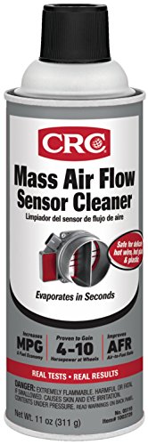
Increases Horsepower And Improves Air/Fuel Ratio And Mpg

Restores Sensor Accuracy & Fuel Economy - By safely removing contaminants like dirt, oil, and pollen from the MAF sensor, the cleaner helps restore the sensor’s ability to measure airflow accurately, which leads to improved fuel combustion.
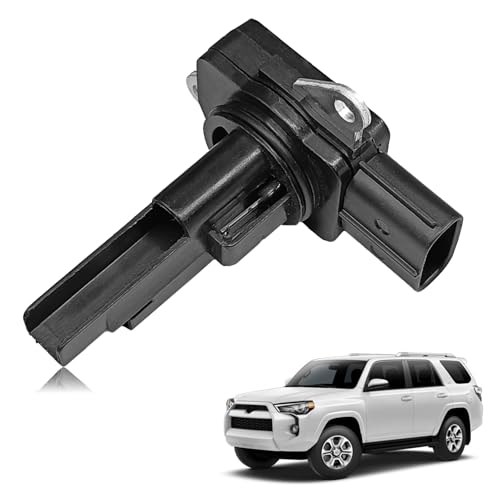
【Compatibility】Compatible with 10-12 HS250h,11-17 CT200h,13-17 ES300h,07-17 ES350 GS350 Camry,08-14 IS F XD,06-15 IS250,16-17 IS300,06-17 IS350,13-18 GS450h,07-15 RX350,etc, please kindly check the detail models in the product description below.
When Should You Replace the MAF Sensor Instead of Cleaning It?
Cleaning a MAF sensor only resolves issues caused by dry dust, pollen, or light oil films on the heated sensing wire. Cleaning will not repair internal electronic component failures, cracked substrate chips, or mechanical wear.
Replace the sensor immediately under any of the following verified conditions:
- The sensor casing, mounting flange, or electrical connector housing is cracked, melted, or physically damaged.
- Scan tool airflow data remains fixed at 0.0 g/s, jumps erratically, or fails to rise smoothly with throttle openings despite verified +12V power, clean ground, and good harness continuity.
- Dynamic WOT peak airflow remains more than 20% below target horsepower calculations after thorough cleaning and intake leak verification.
- The internal IAT thermistor reports open-circuit (-40°C / -40°F) or short-circuit (+140°C / +284°F) values.
Always source direct-fit OEM units or certified DENSO equivalents matched to your exact VIN. Genuine part specifications can be referenced via the Toyota Official Parts Catalog. Generic aftermarket “white-box” sensors frequently exhibit inaccurate output calibration curves that cause persistent P0101 and P0171 codes.
[Products Worth Considering]

Replacement for 2000-2004 Avalon 3.0L, 2000-2004 Tundra 3.4L & 05-10 Tundra 4.0L, 1999-04 Tacoma 3.4L & 05-2010 Tacoma 4.0L, 00-03 RAV4 2.0L, ES30 RX300 3.0L 99-03, ES330 RX330 3.3L 04-05, GS300 3.0L LS430 4.3L 01-05, Scion XA 04-06, XB 04 TC 05 2.4L. FAERSI MAF Direct Replacement for the OEM factory Mass Air Flow Sensor.Every product must take inspected and Over 3000 hours product test. If the maf is malfunction or damage, please contact us for a refund or replacement.

Direct OE Replacement MAF Sensor: Replaces OE part numbers 22204-21010, 197-6020, L321-13-215, 45-1095, 336-05231, 917-817, 158-0777, 74-50009; precision-engineered as a drop-in replacement with no modifications required

ReplacesOE#: 22204-07010, 222040C020, 22204-0D030, 22204-22010, 336-05231, 336-60525, 336-60557, 3848619061, 74-50009, AF10029, MAS0267, MF4228N, 5S2748, 86138, MF4226N, 19762, MF20129, MAS0313, FDM760, MAS0275, 8ET009142-931, 197-6030, 213-3424, 220129M, 840-951, 1380084E00000, 22204-0L010, 1380084E00.Please compare the original sensor on your car with the picture sensor to make sure you buy the correct one,or you can check the year make model by amazon confirmedfit to make sure the sensor fit your car.
Frequently Asked Questions
What is the primary function of the mass air flow sensor in a Toyota Camry?
The MAF sensor measures the exact mass (weight) of incoming air entering the intake system in grams per second (g/s). The ECM uses this data alongside intake air temperature, throttle position, and engine RPM to calculate precise fuel injection duration and base ignition timing.
What are the classic symptoms of a failing Toyota Camry MAF sensor?
The most common symptoms include rough idle surging, engine stalling at stops, throttle hesitation during acceleration, reduced fuel economy, and Check Engine Light trouble codes P0101, P0102, P0103, or P0171.
Can you drive a Camry with a bad MAF sensor?
You should avoid driving if the vehicle stalls in traffic, hesitates violently, or has a flashing Check Engine Light. If the engine runs smoothly and the light is steady, you may drive a short distance directly to a repair facility while avoiding heavy engine loads.
What should my Toyota Camry MAF read at warm idle?
On a fully warmed engine (coolant temp > 75°C / 167°F) with accessories OFF in Park/Neutral at 650–750 RPM, a 2.5L 4-cylinder should read 1.8 to 2.5 g/s, and a 3.5L V6 should read 2.6 to 3.7 g/s.
Can I clean a Toyota Camry MAF sensor with brake cleaner or carb cleaner?
No. Never use brake cleaner, carburetor cleaner, or aggressive solvents. These chemicals leave residue and melt the internal plastic housing and delicate silicone coatings. Use only dedicated electronic MAF cleaner on older hot-wire sensors, or follow factory low-pressure air cleaning procedures on modern slot-style sensors.
What happens if I unplug the MAF sensor while the engine is running?
Unplugging the sensor forces the ECM into a pre-programmed “limp home” default map using throttle position and engine speed. While the engine may idle smoothly on fallback tables, this does not prove the MAF is defective and immediately sets additional open-circuit diagnostic codes.
Will a bad Camry MAF sensor always trigger a Check Engine Light?
No. A lightly contaminated or skewed MAF sensor can report airflow values that are technically plausible to the ECM but mathematically incorrect by 10% to 15%, causing poor drivability and elevated fuel trims long before setting a DTC.
Should I disconnect the 12V battery after replacing the MAF sensor?
It is recommended to clear codes using an OBD-II scan tool rather than disconnecting the battery. Disconnecting the battery resets all emissions readiness monitors and erases throttle body learned adaptive memory, which can cause erratic idling until re-learned.
Diagnostic Summary and Next Steps
Accurate Toyota Camry MAF sensor diagnosis requires systematic testing rather than speculative parts replacement. Always begin by documenting trouble codes and freeze-frame parameters, inspect the intake boot and PCV lines for unmetered air leaks, and compare live scan tool airflow data (g/s) and fuel trims against factory baseline ranges. If cleaning does not restore airflow accuracy or circuit tests fail, install a VIN-matched OEM or DENSO replacement. If persistent lean codes remain, consult our dedicated Toyota Camry P0171 lean code diagnostic guide; for idle-specific shutoffs, follow our Camry stalling troubleshooting procedure.
Authoritative Diagnostic Sources
- DENSO Mass Air Flow Sensors Technical Specification — details hot-wire and bypass channel design, IAT circuit parameters, and sensor cleaning limits.
- Toyota Technical Information System (TIS) — official technical service bulletins, diagnostic trees, and Techstream data list parameters.
- Camry XV70 2GR-FKS MAF On-Vehicle Inspection Manual — published factory idle and raised RPM airflow benchmark values.
- Toyota Camry MAF Circuit Electrical Diagnostic Flow — diagnostic logic for DTC P0102 and P0103 circuit faults.
- Toyota Camry MAF Signal Plausibility Diagnostic Flow — factory validation checks for DTC P0101 plausibility failures.
- Toyota Genuine Parts Catalog: Intake Air Flow Meter Sub-Assembly — OEM part numbers and exact vehicle fitment criteria.