Your Toyota Tacoma’s oxygen (O2) sensors and air-fuel ratio (A/F) sensors help the engine computer manage fuel trim, protect the catalytic converter, and keep emissions in check. Upstream sensors give the ECM feedback for air-fuel control, while downstream sensors help verify catalyst performance. If your Tacoma has poor fuel economy, a rough idle, failed emissions readiness, or a check-engine light with codes such as P0135 or P0141, start with a scan-tool check, wiring inspection, heater-circuit test, and model-specific service information before replacing parts.
Quick Answer
Tacoma O2 and A/F sensors measure oxygen in the exhaust so the ECM can adjust fuel delivery and monitor catalytic-converter efficiency. Upstream A/F sensors control mixture; downstream O2 sensors check the catalyst. Diagnose them with an OBD-II scan, live data, wiring checks, exhaust-leak inspection, and heater-circuit testing.
Key Takeaways
- Bank 1 is the side with cylinder 1; V6 Tacomas also have Bank 2, while four-cylinder models have only one bank.
- Upstream sensors are before the catalytic converter and affect fuel trim; downstream sensors are after the converter and mainly monitor catalyst efficiency.
- Many newer Tacomas use wideband A/F sensors upstream and narrowband O2 sensors downstream, so voltage readings are not interpreted the same way.
- Heater-circuit faults can make a good sensor look bad because the sensor must reach operating temperature before its signal is reliable.
- Use OEM-quality, location-specific sensors and confirm the root cause before replacing parts.
At a Glance
| Time Required | 30–60 minutes for diagnosis; about 1–2 hours for replacement if the sensor is accessible |
| Difficulty | Beginner to intermediate, depending on rust and sensor access |
| Tools Needed | OBD-II scanner with live data, digital multimeter, 22 mm oxygen-sensor socket or wrench, penetrating oil, jack stands or ramps, safety glasses |
| Typical Cost | Parts vary by model year, engine, emissions package, and sensor location; labor is higher when sensors are seized or hard to reach |
Who This Guide Is For and What You’ll Learn
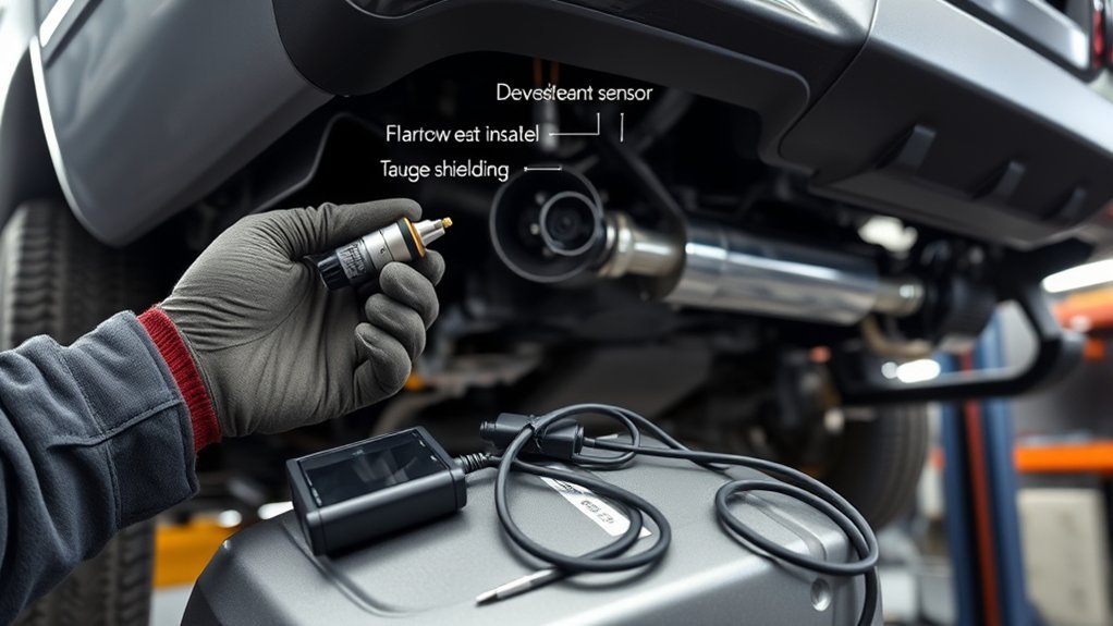
If you own, maintain, or repair a Toyota Tacoma, this guide explains what the oxygen and air-fuel ratio sensors do, where they are located, how to read common sensor data, and how to decide whether diagnosis or replacement makes sense. You’ll learn the difference between upstream and downstream sensors, how Bank 1 and Bank 2 are identified, why sensor heaters matter, and which checks to perform before buying a new sensor.
The goal is practical: confirm the fault, avoid replacing the wrong sensor, and protect the engine, catalytic converter, and emissions system. Sensor names, part numbers, wiring colors, and test values vary by model year, engine, drivetrain, and emissions certification, so always confirm final specifications with the correct Toyota repair information or parts catalog for your VIN.
Toyota Tacoma O2/A-F Sensor Locations
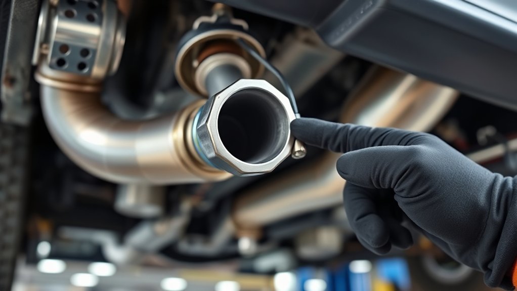
Most modern Tacomas use sensors before and after the catalytic converter. The exact count depends on the engine and model year. A four-cylinder Tacoma normally has one bank with an upstream sensor and a downstream sensor. A V6 Tacoma normally has Bank 1 and Bank 2, with sensors on both exhaust banks.
Toyota and many parts manufacturers use “Sensor 1” for the sensor before the catalytic converter and “Sensor 2” for the sensor after the catalytic converter. On many newer Tacoma applications, Sensor 1 is an air-fuel ratio sensor rather than a traditional narrowband oxygen sensor.
Bank Identification Locations
Bank identification matters because replacing “Bank 1 Sensor 1” when the code points to “Bank 2 Sensor 1” wastes time and money. Bank 1 is always the side of the engine that contains cylinder 1. Bank 2 exists only on V-type engines and is the opposite bank.
- Find Bank 1 first: Use the cylinder layout for your Tacoma’s engine. Do not guess by driver side or passenger side because layouts differ by engine.
- Identify Sensor 1: Sensor 1 is upstream, before the catalytic converter. It is used for air-fuel feedback.
- Identify Sensor 2: Sensor 2 is downstream, after the catalytic converter. It is mainly used to monitor catalyst performance.
- Confirm with the connector and part number: Wire length, connector shape, and sensor calibration can differ by bank and position.
Note: The fastest way to avoid ordering the wrong sensor is to search by VIN and match the exact bank, sensor position, engine, and emissions package.
Upstream Vs Downstream
Upstream sensors sit before the catalytic converter. Their readings help the ECM adjust injector pulse width and keep the air-fuel mixture near the target range. On many newer Toyota systems, these upstream units are wideband A/F sensors, which provide more detailed mixture feedback than older narrowband oxygen sensors.
Downstream sensors sit after the catalytic converter. Their job is different: they help the OBD-II system determine whether the catalytic converter is storing oxygen and cleaning exhaust effectively. A downstream sensor should usually show a steadier pattern than an upstream narrowband sensor once the engine and catalyst are warm.
Sensor Heater Wiring
O2 and A/F sensors need heat before their signal is useful. Built-in heaters help them reach operating temperature quickly, shorten open-loop operation, and allow the ECM to use sensor feedback sooner after startup. Heater-circuit failures can trigger codes such as P0135, P0141, P0155, or P0161 depending on bank and position.
- Inspect: Check the connector, pins, harness clips, and wiring near hot exhaust parts.
- Test: Verify heater power, ground, and resistance according to the correct service specification.
- Repair: Use proper terminals, heat-resistant routing, and sealed repairs. Do not twist wires together near the exhaust and call it fixed.
Warning: Exhaust parts can stay hot long after shutdown. Let the exhaust cool, support the truck safely on stands or ramps, and never work under a vehicle held only by a jack.
Cold Start and Open-Loop vs Closed-Loop Behavior
During a cold start, your Tacoma may run in open-loop mode. In open loop, the ECM uses programmed fuel strategy and sensor inputs such as coolant temperature, intake air temperature, and airflow rather than relying fully on oxygen-sensor feedback. This helps the engine start, idle, and warm the catalyst quickly.
As the engine, sensors, and catalyst warm up, the system moves toward closed-loop operation. In closed loop, the ECM uses oxygen or A/F sensor feedback to fine-tune fuel delivery. That feedback helps reduce excess fuel use, improve drivability, and lower emissions.
If a heater circuit fails, the sensor warms slowly or may not reach operating temperature at the expected time. That can extend open-loop behavior, slow fuel-trim correction, and trigger an emissions-related diagnostic trouble code.
[Products Worth Considering]
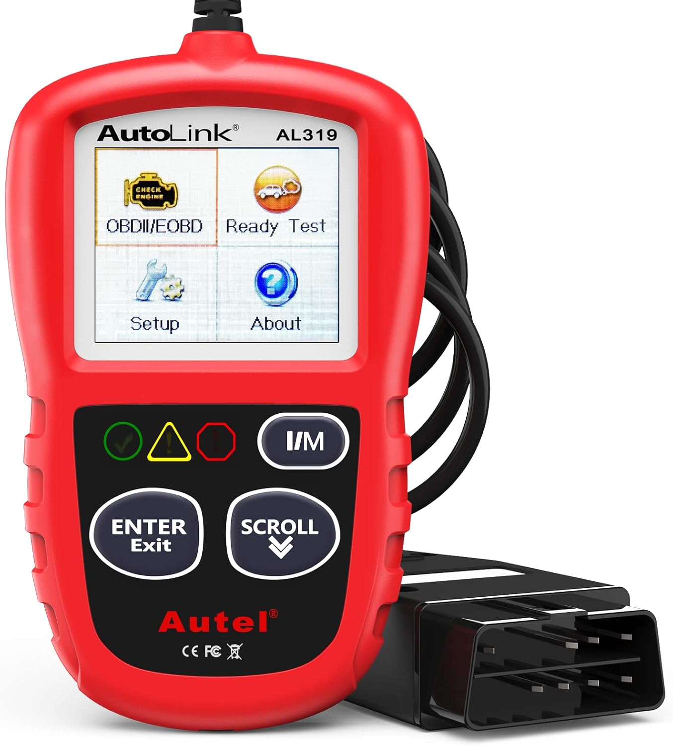
The Autel AL319 is a user-friendly OBD2 scan tool designed to help drivers quickly diagnose check engine light issues and understand vehicle fault codes. It supports reading and clearing DTCs, live data, freeze frame, I/M readiness, and vehicle information, making it a practical choice for DIYers and everyday car owners. With plug-and-play operation, a color display, built-in speaker, and broad vehicle compatibility, it delivers fast, reliable diagnostics without complicated setup.

The AICEL TPMS Relearn Tool helps quickly reset and relearn tire pressure sensors on compatible GM vehicles after tire rotation, sensor replacement, or warning light issues. Designed for easy handheld use, it works with most cars, SUVs, and pickup trucks and can save time by eliminating unnecessary trips to the auto store. Its durable ABS housing and simple activation process make it a practical tool for keeping the tire pressure monitoring system operating properly.

The TOPDON BT100 helps you quickly check the health and charge status of 12V lead-acid batteries with clear analytical results, including state of health, state of charge, voltage, and cranking performance. It supports a wide range of battery types and vehicles, making it a practical tool for diagnosing starting and charging issues at home or in the shop. Compact and easy to use, it provides fast, reliable testing without needing to charge the device first.
Reading Voltages: Interpreting Lean vs Rich Tacoma Sensors
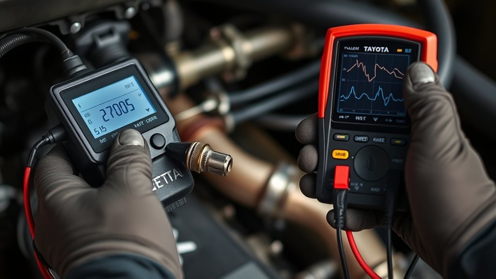
Sensor voltage is useful only when you know which sensor type you are viewing. A traditional narrowband oxygen sensor often switches low-to-high as the mixture moves lean-to-rich. A wideband A/F sensor works differently and may be displayed by a scan tool as voltage, current, equivalence ratio, lambda, or commanded/actual air-fuel data.
For that reason, do not condemn a Tacoma sensor from one generic voltage number alone. Look at the correct data PID, compare Bank 1 and Bank 2 behavior on V6 models, check fuel trims, and follow the diagnostic steps for the exact code.
Voltage Ranges Explained
A warm narrowband oxygen sensor commonly switches roughly between low voltage for lean and high voltage for rich. A typical range often discussed for narrowband sensors is about 0.1–0.9 volts, but the exact pattern and switching rate matter more than a single snapshot.
A Toyota-style A/F sensor is not read the same way. Many scan tools show A/F sensor voltage near a midrange value at stoichiometric operation, while other tools show current or lambda. Depending on the scan tool, a lean condition may appear as a higher value, lower value, positive current, or negative current. Always use the service information for your sensor type before interpreting the reading.
| Sensor Type | Common Location | Typical Use | How to Interpret |
|---|---|---|---|
| Air-fuel ratio sensor | Upstream on many newer Tacomas | Fuel-control feedback | Use scan-tool PIDs and service data; do not treat it like a narrowband O2 sensor |
| Narrowband oxygen sensor | Downstream on many newer Tacomas | Catalyst monitoring | Look for expected warm behavior and compare to upstream activity |
Lean Vs Rich Signals
A lean mixture has more oxygen left in the exhaust. A rich mixture has less oxygen left because more fuel was present during combustion. The ECM uses this information to correct short-term and long-term fuel trims.
Common clues include:
- Lean condition: Positive fuel trims, intake or vacuum leaks, exhaust leaks before the sensor, low fuel pressure, dirty mass-airflow sensor, or unmetered air.
- Rich condition: Negative fuel trims, leaking injector, excessive fuel pressure, restricted air intake, contaminated sensor, or incorrect sensor signal.
- Sensor fault: Slow response, stuck readings, heater-code failure, damaged wiring, or readings that do not respond when the mixture changes.
Heater Influence On Readings
The heater brings the sensor up to temperature quickly. Until the sensor is hot enough, its readings can be slow, biased, or ignored by the ECM. This is why heater codes should be taken seriously even when the engine seems to run normally.
- Check for heater-related diagnostic trouble codes before interpreting sensor data.
- Verify the sensor reaches active operation within the expected time.
- Inspect the harness near the exhaust, because melted wiring can mimic a failed sensor.
A sensor code tells you which circuit or signal failed a test; it does not automatically prove the sensor itself is the only bad part.
Symptoms, Heater Codes, and 5 Quick Diagnostics
A failing Tacoma O2 or A/F sensor can cause poor fuel economy, rough idle, hesitation, increased emissions, failed readiness monitors, or an illuminated check-engine light. However, the same symptoms can also come from vacuum leaks, exhaust leaks, ignition problems, dirty airflow sensors, fuel-pressure issues, or catalytic-converter problems.
| Quick Check | What to Do | Why It Matters |
|---|---|---|
| Scan codes | Record all stored, pending, and permanent codes | Related codes can point to wiring, fuel trim, misfire, or catalyst issues |
| Check live data | Review A/F sensor data, O2 data, fuel trims, coolant temperature, and readiness monitors | Live data shows whether the sensor responds after warm-up |
| Inspect wiring | Look for melted insulation, corrosion, loose pins, or damaged connectors | Wiring faults can set the same codes as failed sensors |
| Check exhaust leaks | Inspect leaks near manifolds, flanges, gaskets, and sensor bungs | Outside air entering the exhaust can create false lean readings |
| Test heater circuit | Measure power, ground, and resistance per service data | A cold sensor cannot report accurately at the expected time |
[Products Worth Considering]
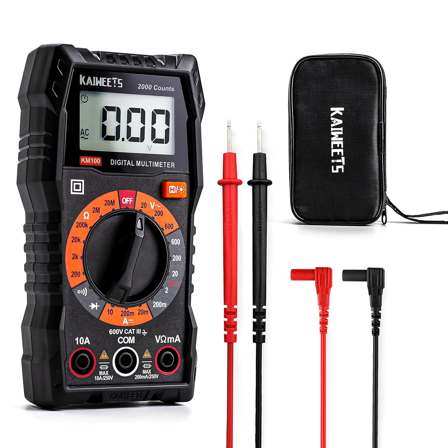
This KAIWEETS digital multimeter is a versatile tool for measuring AC/DC voltage, DC current, resistance, continuity, and diodes in home, automotive, and electrical applications. It includes pre-installed batteries, a carrying case, test leads, data hold, backlight, and overload protection for easier and safer everyday testing. Built with double fuses and rated for broad household and light professional use, it helps users diagnose electrical issues with confidence.

The ANENG SZ301 digital multimeter is a versatile testing tool for measuring AC/DC voltage, current, resistance, continuity, diode, capacitance, and live wire detection. It features a clear display, precise readings, and built-in safety protections including double fuses and overload protection, making it useful for electronics, automotive work, and household electrical troubleshooting. The kit includes a protective silicone case, test leads, and pre-installed batteries for convenient use right out of the box.
Common Tacoma O2 and A/F Sensor Codes
Exact code definitions can vary slightly by scan tool, but these are common oxygen-sensor and heater-circuit families you may see:
- P0130–P0134: Bank 1 Sensor 1 signal-related faults.
- P0135: Bank 1 Sensor 1 heater-circuit fault.
- P0136–P0141: Bank 1 Sensor 2 signal or heater-related faults.
- P0150–P0155: Bank 2 Sensor 1 signal or heater-related faults on V6 models.
- P0156–P0161: Bank 2 Sensor 2 signal or heater-related faults on V6 models.
- P0420/P0430: Catalyst-efficiency codes. These may involve downstream sensor data, but the catalytic converter, exhaust leaks, fuel control, and misfires must also be checked.
Pro Tip: Save freeze-frame data before clearing codes. Freeze-frame shows engine temperature, speed, load, fuel trims, and other conditions from the moment the fault was detected.
Replace It Yourself? When to DIY vs Call a Shop
Replacing an oxygen or A/F sensor can be a reasonable DIY job if the sensor is easy to reach, the truck is safely supported, and you have confirmed the diagnosis. Many Tacoma sensors use a 22 mm hex, and an oxygen-sensor socket makes removal easier around the harness.
Call a shop when the sensor is seized, access is poor, the code points to a circuit problem you cannot test, the threads are damaged, or the truck has catalyst-efficiency or fuel-trim codes that require deeper diagnosis. A shop can also confirm whether the issue is the sensor, wiring, exhaust leak, fuel control, or catalytic converter.
- DIY makes sense when: You have a confirmed sensor or heater fault, safe lifting equipment, a scan tool, and the correct replacement sensor.
- Professional diagnosis makes sense when: The code returns after replacement, multiple fuel-trim or misfire codes are present, or the sensor is difficult to remove.
- Use the right part: Match the sensor to bank, position, engine, model year, and emissions certification. Upstream A/F sensors and downstream O2 sensors are not interchangeable.
Practical Replacement Tips: Tools, Socket Sizes, and Stuck-Sensor Tricks
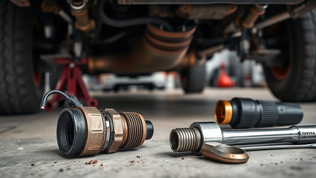
Once you have confirmed the correct sensor, gather the tools before the exhaust cools completely or after it cools fully, depending on access and rust. A slightly warm exhaust can sometimes help loosen a stubborn sensor, but it also increases burn risk. Safety comes first.
- Disconnect the battery if required by your service procedure: Keep radio codes, settings, and relearn procedures in mind.
- Unplug the sensor connector first: Do not twist the harness while loosening the sensor.
- Use penetrating oil on the threads: Let it soak, especially on high-mileage or rusty trucks.
- Use the correct socket: A 22 mm oxygen-sensor socket or wrench fits many applications, but always confirm fit before forcing it.
- Compare old and new sensors: Connector, wire length, thread size, and sensor body must match.
- Protect the tip: Do not touch or contaminate the sensing element.
- Use anti-seize only if appropriate: Many new sensors already have the correct compound on the threads. Keep anti-seize away from the sensor tip.
- Torque to specification: Over-tightening can damage threads; under-tightening can cause exhaust leaks.
- Clear codes and verify repair: Check live data and confirm the readiness monitor runs after the correct drive cycle.
Warning: Do not use an open flame near penetrating oil, fuel vapors, wiring, or underbody materials. If the sensor bung or manifold threads start to strip, stop and get professional help.
After Replacement Checks and Readiness Monitors
After replacing a sensor, do not assume the repair is complete just because the check-engine light is off. Clear the codes only after saving diagnostic data, then run the vehicle long enough for the ECM to retest the system. OBD-II readiness monitors may show “not ready” until the required drive conditions are met.
Use your scan tool to verify:
- The original code does not return as pending or confirmed.
- Fuel trims are reasonable after warm-up.
- The A/F or O2 sensor responds normally in live data.
- The oxygen-sensor, oxygen-sensor-heater, and catalyst monitors complete when conditions allow.
- No misfire, fuel-system, or exhaust-leak symptoms remain.
Mistakes to Avoid
- Replacing a sensor only because a code names it: Test the circuit and inspect for leaks first.
- Mixing up Bank 1 and Bank 2: Confirm cylinder 1 location before ordering parts.
- Using the wrong sensor type: A/F sensors and O2 sensors are not the same.
- Ignoring heater codes: Heater faults affect sensor warm-up and emissions readiness.
- Skipping exhaust-leak checks: A small leak can cause false lean readings and repeated codes.
- Using universal sensors carelessly: Incorrect splicing or calibration can create new problems.
Frequently Asked Questions
What is the main function of an oxygen sensor?
An oxygen sensor measures oxygen in the exhaust stream. The engine computer uses that information to adjust fuel delivery, monitor emissions performance, and help protect the catalytic converter.
What does an air-fuel ratio sensor do in a Toyota Tacoma?
An air-fuel ratio sensor gives the ECM more precise mixture feedback than a traditional narrowband O2 sensor. On many newer Tacomas, upstream sensors are A/F sensors used for fuel-control corrections.
What should oxygen sensors read at idle?
A warm narrowband O2 sensor often switches between low and high voltage as the mixture changes, but many Tacoma upstream sensors are A/F sensors and should not be judged by the same 0.1–0.9 volt rule. Use the correct live-data PID and service information for your model.
Can I drive with a bad O2 or A/F sensor?
The truck may still run, but driving with a failed sensor can reduce fuel economy, increase emissions, prevent readiness monitors from completing, and in some cases contribute to catalytic-converter damage. Diagnose and repair the fault as soon as practical.
Should I replace all Tacoma oxygen sensors at once?
Usually no. Replace the sensor that has been properly diagnosed as faulty. Replacing all sensors can be expensive and may not fix the real issue if the problem is wiring, an exhaust leak, fuel control, or the catalytic converter.
Is Bank 1 always on the driver side?
No. Bank 1 is the side with cylinder 1. Do not identify it by driver side or passenger side without checking the cylinder layout for your exact engine.
Conclusion
Your Tacoma’s O2 and A/F sensors are small parts with a big job: they help the ECM control fuel mixture and verify that the catalytic converter is doing its work. The smartest repair path is not guessing; it is confirming the bank and sensor position, checking live data, inspecting wiring and exhaust leaks, testing the heater circuit, and using the correct replacement part only when the diagnosis supports it. Do that, and you’ll avoid repeat codes, wasted parts, poor fuel economy, and preventable emissions problems.
Sources
- Toyota Owners Manuals and Warranties — official Toyota owner-manual and vehicle-information source.
- Toyota Technical Information System — official repair information source for model-specific diagnostic and torque specifications.
- DENSO O2 and A/F Sensor Troubleshooting — sensor location, bank identification, and diagnostic guidance.
- DENSO A/F Sensors — explanation of air-fuel ratio sensor function and mixture-control role.
- U.S. EPA OBD Regulations and Requirements — background on OBD monitoring of oxygen sensors, catalyst systems, fuel trim, and heater circuits.
- California Bureau of Automotive Repair OBD Test Reference — readiness-monitor and OBD inspection reference information.