Last updated: September 16, 2026
How this guide was checked: This is a documentation-based guide, not a claim of hands-on testing. This revision cross-checks Toyota campaign documents, Toyota parts information, factory repair-manual information, current replacement-part fitment, and ball-joint manufacturer guidance. Use Toyota TIS for the exact VIN- and model-year-specific procedure, torque values, and non-reusable hardware rules.
Toyota Tacoma lower ball joint replacement has more than one repair path. On many 1995–2004 Tacoma 4WD and PreRunner trucks, the lower ball joint is a complete, side-specific bolt-on assembly; some first-generation 2WD layouts use different bolt-on hardware and should be verified separately. For 2005–2023 trucks, Toyota factory service information treats the lower ball joint as part of the lower control arm, while aftermarket suppliers also sell standalone press-in lower joints for these years. The separately listed lower-ball-joint attachment or steering-stop bracket is not the ball joint itself. Identify the exact model year, drivetrain, side, part style, and service procedure before removing anything. This guide does not provide a 2024-and-newer Tacoma procedure.
Quick Answer
First determine which repair path applies. Many 1995–2004 4WD and PreRunner trucks use a side-specific bolt-on lower-ball-joint assembly. For 2005–2023 trucks, the Toyota factory repair path commonly treats the joint as part of the lower control arm, while aftermarket suppliers offer press-in replacement joints that use the existing arm and a retaining ring. The separate lower-ball-joint attachment or steering-stop bracket is a different component. Chock the wheels, support the truck on rated jack stands, support the steering knuckle, use new cotter pins, and tighten every disturbed fastener to the exact model-specific specification.
Key Takeaways
- Confirm the model year, drivetrain, side, replacement-part style, hardware rules, and service procedure before ordering parts or renting a press.
- On 2005–2023 trucks, the lower-ball-joint attachment or steering-stop bracket is separate from the joint; Toyota factory service information commonly treats the joint itself as part of the lower control arm, while aftermarket suppliers offer standalone press-in joints.
- A first-generation bolt-on assembly, an aftermarket press-in joint, and a complete lower control arm require different tools, parts, and disassembly.
- Certain 2001 through mid-2004 Tacoma 4WD and PreRunner vehicles were included in Toyota campaign 50J. Eligibility is VIN-specific.
- Never let the steering knuckle hang from the brake hose, ABS wire, or CV axle.
- Do not use one online torque table for every Tacoma. Verify every disturbed fastener through Toyota TIS or the correct factory repair manual.
At a Glance
| Scope | Common 1995–2023 Tacoma lower-ball-joint service concepts; exact procedures vary by generation, drivetrain, side, and replacement part |
| 1995–2004 4WD/PreRunner Path | Commonly a complete, side-specific bolt-on lower-ball-joint assembly; verify other first-generation layouts separately |
| 2005–2023 Path | Toyota factory service path commonly replaces the lower control arm when the joint fails inspection; aftermarket suppliers also sell press-in lower joints for the original arm |
| Separate Attachment | The side-specific lower-ball-joint attachment or steering-stop bracket at the stud/knuckle is a separate service part and is not the joint itself |
| Time Required | Several hours for one side; corrosion, seized tapers, damaged hardware, press setup, and first-time work can extend the job |
| Difficulty | Intermediate to advanced DIY; steering- and suspension-critical |
| Common Tools | Floor jack, rated jack stands, wheel chocks, sockets, breaker bar, torque wrench, pliers, taper separator, wire brush, and support wire or stand for the knuckle |
| Press Tools | Ball-joint press, correctly sized receiver and installer cups, and snap-ring pliers only when using a standalone aftermarket press-in joint |
| Alignment | Check after repair; measurement and adjustment are especially important when a complete control arm, control-arm cams, tie-rod adjustment, or ride height was disturbed |
Repair-Path Rule: If you are following Toyota factory service information for a 2005–2023 Tacoma, expect the lower joint to be serviced with the lower control arm when it fails inspection. If you are installing a standalone aftermarket press-in joint, follow that joint manufacturer’s fitment, orientation, pressing, and retaining-ring instructions and reject any damaged or loose control-arm bore.
Warning: A lower ball joint carries steering and suspension load. Incorrect parts, an unseated taper, loose mounting hardware, a damaged control-arm bore, a missing cotter pin, or an improperly seated snap ring can cause loss of steering control. Stop and use a qualified mechanic when the correct component style, lifting point, press setup, bore condition, or torque specification is uncertain.
Which Toyota Tacoma Lower Ball Joint Replacement Procedure Applies?
Before choosing tools, identify every component in the repair area. A first-generation bolt-on lower-ball-joint assembly includes the joint and its side-specific mounting body as one replacement unit. On 2005–2023 trucks, the ball-joint stud is part of the lower-control-arm area and connects to a separate side-specific attachment, sometimes called the steering stop in repair discussions, which bolts to the steering knuckle. Toyota factory service information commonly directs replacement of the lower control arm when the lower joint fails inspection; standalone press-in joints are an aftermarket service option.
A complete lower control arm includes the arm, bushings, and, when specified by the supplier, the lower ball joint. On many 2005–2023 applications, this is the repair path that most closely follows Toyota factory service information. It avoids pressing a new joint into an old bore but requires control-arm removal and makes alignment measurement especially important.
| Tacoma Group or Part Style | Common Replacement Path | What to Verify |
|---|---|---|
| 1995–2004 4WD and PreRunner | Commonly a complete, side-specific bolt-on lower-ball-joint assembly | Exact year, drivetrain, left or right side, mounting-bolt style, recall status, and service-manual sequence |
| Other 1995–2004 layouts | Some 2WD/5-lug trucks use different bolt-on hardware and geometry; do not assume the 4WD/PreRunner campaign procedure applies | VIN, 5-lug vs. 6-lug layout, drivetrain, side, mounting-bolt count, replacement-part shape, and factory procedure |
| 2005–2023 standalone aftermarket lower joint | Use a press only when the replacement supplier specifically lists a press-in lower joint for the exact Tacoma and provides installation guidance | Exact fitment, control-arm bore condition, orientation marks, retaining ring, press cups, attachment clearance, and supplier/Toyota torque requirements |
| 2005–2023 separate attachment | The attachment or steering stop is separate from the ball joint and is normally reused unless damaged or replacement is specified | Left or right side, mounting-hole pattern, stud taper fit, contact damage, bolt condition, and service-manual instructions |
| Complete lower control arm | For many 2005–2023 trucks, this is the Toyota-style service path when the lower joint fails inspection; it also replaces the arm bushings | Drivetrain, side, bushing design, joint inclusion, cam hardware, ride-height tightening rules, and alignment |
| 2024 and newer | Not covered by this procedure | Use Toyota TIS or the repair manual for the redesigned truck |
Place the old and replacement parts side by side before installation. Confirm left or right orientation, mounting-hole spacing, stud size, taper position, boot clearance, grease-fitting location if equipped, and all supplied hardware. If you are using a standalone aftermarket joint, also confirm the press-fit diameter, retaining-ring groove, and manufacturer-required orientation. Stop if the parts do not match.
Check Recall Status and Service Information Before Buying Parts
Use the official Toyota Technical Information System or the correct factory repair manual for removal steps, non-reusable hardware rules, tightening sequences, and torque specifications. Use Toyota Owners Manuals and Warranties for owner-level information such as approved lifting points, wheel installation guidance, and maintenance inspection information.
Certain 2001 through mid-2004 Tacoma 4WD and PreRunner vehicles were included in Toyota Special Service Campaign 50J, NHTSA campaign 05V225000. Toyota’s campaign documents list an affected Tacoma production period of July 31, 2001 through December 23, 2003 and explain that the ball surface could have been scratched during manufacturing. The affected joint could then develop excessive wear and looseness, increased steering effort, reduced self-centering, or front-suspension noise. In an extreme case, the lower joint could separate and cause loss of steering control.
Toyota’s campaign remedy replaced both front lower ball joints and then called for inspection and adjustment of the front-end alignment. That campaign workflow applies to eligible VINs and should not be treated as a universal requirement to replace both sides during every non-recall repair.
Not every Tacoma in the stated model-year range is covered. Check the VIN through the Toyota recall lookup and the NHTSA recall lookup before paying for the repair. NHTSA states that a safety recall itself does not expire; the VIN lookup shows whether an unrepaired recall is still open for a specific vehicle.
Recall Tip: If the VIN shows an open lower-ball-joint campaign, contact a Toyota dealer before buying parts or beginning DIY work. Recall remedies are handled through the manufacturer’s campaign process.
How Can You Confirm a Tacoma Lower Ball Joint Is Bad?
A clunk does not prove that the lower ball joint has failed. Similar symptoms can come from a wheel bearing, outer or inner tie rod, sway-bar link, control-arm bushing, shock mount, loose wheel, CV joint, steering rack, or brake hardware.
With the truck on the ground, inspect the lower-ball-joint boot for tears, missing clamps, grease leakage, rust-colored powder, distortion, or contact damage. Note whether the steering feels loose, fails to self-center, wanders, or makes noise during low-speed turns and suspension movement.
After lifting the truck at the correct points and transferring its weight to jack stands, compare both front corners. Have a helper rock the wheel while you watch the joint, tie rod, hub, control arm, and attachment area. The correct loaded or unloaded ball-joint test varies by suspension design. Toyota factory information for some 2005–2023 applications treats excessive lower-joint play as a reason to replace the lower control arm, so use the exact Toyota procedure for your model year rather than diagnosing the joint from wheel movement alone.
Do not drive the truck when the joint stud or housing shows visible movement, the boot has separated and the joint is contaminated, the wheel changes position under load, or the suspension has partially separated. Arrange towing or professional inspection instead.
If the movement appears to come from the hub instead of the ball joint, use the site’s Tacoma wheel-bearing diagnosis guide before ordering suspension parts.
Pro Tip: Photograph the assembly before disassembly. Capture cotter-pin direction, washer order, wire and hose routing, attachment orientation, press-in joint orientation marks, and the position of every bracket you will remove.
What Tools and Parts Do You Need?
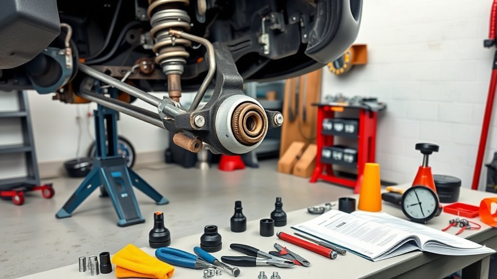
Gather the common safety and hand tools first. Add press equipment only after confirming that you are installing a compatible standalone aftermarket press-in joint.
- Floor jack rated for the truck
- Jack stands with adequate load rating
- Wheel chocks
- Safety glasses and mechanic gloves
- Correct sockets and wrenches for the model-specific procedure
- Breaker bar and calibrated torque wrench covering every required torque range
- Screw-type ball-joint or tie-rod separator
- Hammer and punch for controlled use only on approved non-threaded areas
- Pliers for cotter pins
- Wire brush, rags, and penetrating oil for external corrosion
- Wire, strap, or stand for supporting the steering knuckle
- Replacement first-generation bolt-on assembly, standalone aftermarket press-in joint, separate attachment, or complete lower control arm matched by VIN, drivetrain, side, and repair path
- New cotter pins, retaining ring when supplied, and every nut or bolt identified as non-reusable
For a standalone aftermarket press-in joint, also obtain the press equipment specified by the joint manufacturer, typically a ball-joint press, correctly sized receiver and installer cups, and retaining-ring pliers. The installer cup must apply force only to the replacement manufacturer’s approved mounting flange or housing surface. It must not press on the stud, boot, grease fitting, closure area, or an unsupported edge of the control arm.
If you are replacing a complete lower control arm, confirm whether new cam bolts, cam plates, nuts, joint hardware, and sway-bar or shock hardware are required. Corroded or seized alignment cams can add significant time and may require professional equipment.
Jack Safety: Work on a firm, level surface. Set the parking brake, chock the wheels that remain on the ground, use the lift points specified for your Tacoma, and transfer the truck’s full weight to rated jack stands. See the site’s Tacoma jack and jack-stand placement guide. Never work under or beside a truck supported only by a hydraulic jack.
The CDC/NIOSH-hosted jack safety sheet advises inspecting lifting equipment, following its manufacturer’s instructions, using sufficient load ratings, and transferring the vehicle’s weight to jack stands. OSHA 29 CFR 1910.244 requires sufficient jack capacity and says a raised load must be cribbed, blocked, or otherwise secured at once.
How Should You Prepare the Tacoma for Ball Joint Removal?
- Park and secure the truck. Use level pavement or concrete, set the parking brake, place the transmission in Park or in gear, and chock the wheels that stay on the ground.
- Loosen the wheel nuts. Break them loose slightly while the tire is still touching the ground.
- Raise and support the truck. Lift at the approved point, place rated jack stands at approved support points, lower the truck onto them, and confirm stability before removing the wheel.
- Remove the wheel and inspect the area. Look for damaged brake hoses, ABS wiring, CV boots, loose tie rods, leaking shocks, bent attachments, damaged control arms, and impact damage before continuing.
- Support the knuckle. Position a stand or support wire so the steering knuckle cannot fall or hang from the brake hose, ABS wire, or CV axle when the taper releases.
- Mark and photograph routing. Record brackets, wire clips, washers, cotter pins, orientation marks, and hardware direction.
Warning: Do not hammer directly on a reusable threaded stud. Do not use the brake hose, ABS wire, CV axle, or steering linkage as a support point.
Which Parts Must You Disconnect Before Removing the Joint?
Disconnect only the components required by the correct Toyota or replacement-part procedure. The access path depends on the generation, drivetrain, and whether you are replacing a first-generation bolt-on assembly, a standalone aftermarket 2005–2023 press-in joint, or the complete lower control arm.
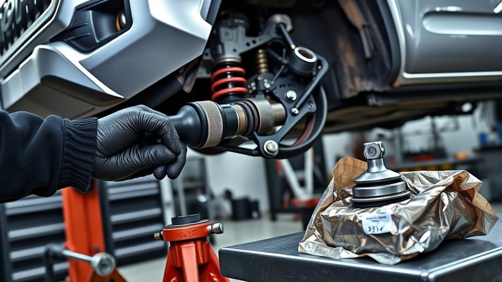
On a common first-generation 4WD or PreRunner assembly, the outer tie rod connects to the lower-ball-joint assembly. That layout normally requires removal of the tie-rod cotter pin and castle nut, separation of the tie-rod taper, separation of the lower-ball-joint stud from the lower control arm, and removal of the bolts connecting the assembly to the steering knuckle.
On a 2005–2023 layout, the lower-joint stud connects to the separate lower-ball-joint attachment or steering-stop bracket, and that attachment bolts to the steering knuckle. If you are following Toyota factory service information, the repair commonly proceeds through lower-control-arm removal or replacement. If you are using a standalone aftermarket press-in joint, the access procedure must also create a square, supported press path through the arm.
Do not automatically remove the axle nut, outer tie rod, sway-bar link, shock, or entire steering knuckle unless the model-specific procedure or required press access calls for it. If the complete lower control arm is being replaced, additional control-arm, shock, sway-bar, and alignment-cam hardware may have to be removed.
When a cotter pin is removed, discard it. Loosen a castle nut while the stud is supported, but leave the nut threaded several turns during taper separation so the assembly cannot release violently. Use a suitable puller or screw-type separator on the taper.
How Do You Replace a Bolt-On First-Generation Lower Ball Joint Assembly?
Use this path only when the replacement part is a complete, side-specific lower-ball-joint assembly, as found on common 1995–2004 Tacoma 4WD and PreRunner layouts. Do not apply this sequence to a 2005–2023 lower-control-arm repair or standalone aftermarket press-in joint merely because the truck also has a part named the lower-ball-joint attachment.
- Verify the replacement. Confirm the model year, drivetrain, side, mounting pattern, stud tapers, boot clearance, and supplied hardware.
- Remove the required access hardware. Follow the VIN-specific procedure and protect all brake, ABS, and CV components.
- Remove the tie-rod cotter pin and loosen its castle nut when applicable. Keep the nut threaded several turns until the taper releases.
- Separate the tie-rod taper. Apply steady force with the correct puller or separator.
- Remove the lower-joint cotter pin and loosen its stud nut. Support the assembly and leave the nut engaged during initial taper separation.
- Separate the lower-joint taper. Strike only an approved knuckle, arm, or attachment boss when the service procedure permits it. Do not hit the threaded stud.
- Remove the assembly-to-knuckle bolts. Support the assembly while removing the final fastener. Note bolt direction, washer position, and any bracket captured by the hardware.
- Remove and compare the old assembly. Inspect the mounting surfaces for cracks, elongated holes, heavy rust loss, impact damage, and damaged threads.
- Position the new assembly. Start all bolts and nuts by hand. Do not use a power tool to force crossed or misaligned threads.
If the new assembly does not sit flat against its mounting surface, stop. Check for rust scale, trapped wiring brackets, reversed orientation, incorrect hardware, or the wrong part.
How Do You Replace an Aftermarket 2005–2023 Press-In Lower Ball Joint?
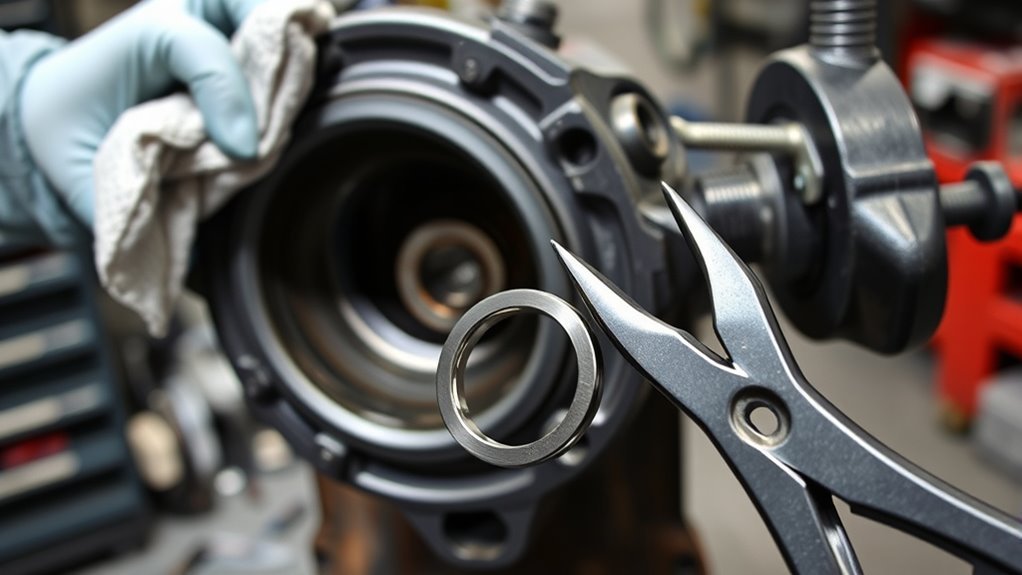
Use this section only when the replacement manufacturer specifically supplies a standalone press-in front lower joint for the exact 2005–2023 Tacoma configuration. This is an aftermarket service path; Toyota factory repair information commonly treats a failed lower joint as part of the lower-control-arm assembly. Confirm the joint’s application, press-fit diameter, orientation instructions, retaining-ring location, and supplied hardware before pressing out the old part.
- Create safe, straight press access. Follow the service procedure for separating the attachment from the joint and moving or removing any components required for a square press setup. Do not load the brake hose, ABS wiring, hub, or CV axle.
- Clean the retaining-ring area. Remove external rust and debris until the entire ring and groove are visible.
- Remove the retaining ring. Use snap-ring pliers or the tool specified by the replacement manufacturer. Do not deeply gouge the groove with a chisel or screwdriver.
- Record joint orientation. Look for manufacturer punch marks, flats, arrows, grease-relief positions, or other directional markings before removal.
- Build a square press setup. The receiver cup must support the surrounding control-arm structure while leaving enough clearance for the joint to exit.
- Press on the approved housing surface. Never load the stud, dust boot, grease fitting, closure area, or an unsupported thin control-arm edge.
- Stop if the joint tilts or binds. Release pressure, realign the cups, and inspect the support surfaces before continuing.
- Inspect the empty bore. Check for cracks, deep gouges, severe corrosion, distortion, an enlarged or visibly oval opening, and damage to the retaining-ring groove.
Reject a Damaged Bore: Do not install a new joint into a cracked, visibly oval, heavily gouged, loose, or otherwise damaged control-arm bore. Replace the lower control arm. A snap ring cannot restore lost press fit or damaged metal.
Ask whether this control arm has already had a joint pressed out. Repeated pressing can reduce bore roundness and retention. A prior replacement does not automatically condemn the arm, but uncertain press history, weak insertion resistance, visible bore damage, poor final fit, or missing supplier guidance are reasons to choose a complete lower-control-arm replacement instead of forcing another joint into the arm.
Clean the usable bore as directed by the replacement manufacturer. Keep the stud taper and its matching attachment seat clean and dry. Do not add grease, anti-seize, or threadlocker to a taper unless the service information specifically calls for it.
| Step | Check | Acceptable Result |
|---|---|---|
| Clean | Bore and retaining-ring groove | No loose rust, burrs, scale, or retained ring fragments |
| Inspect | Lower control arm | No cracks, distortion, deep gouges, severe corrosion, or enlarged bore |
| Orient | Joint body, stud opening, boot, and grease fitting if equipped | Matches the replacement manufacturer’s marks and instructions |
| Support | Press cups and control arm | Force passes through approved structural areas without bending the arm |
| Press | Joint movement | Joint enters squarely and seats fully without loading the boot, stud, or closure area |
| Secure | Retaining ring | Ring is fully engaged around the entire groove |
Position the new joint squarely and tighten the press gradually. Watch the joint from more than one angle and confirm that any orientation marks remain aligned. Once it reaches its specified seat, release the press and inspect the housing shoulder or seating surface.
Install the new retaining ring and verify full engagement around the entire groove. Rotate or probe the ring carefully to confirm that no section is riding above the groove. Install the boot or grease fitting only in the sequence specified by the replacement manufacturer.
Note: If the retaining ring will not seat, the joint may not be fully installed, the groove may contain debris, the joint may be tilted, the control arm may be damaged, or the part may be incorrect. Do not grind the ring or drive with it partly engaged.
Should You Replace the Complete Lower Control Arm Instead?
A complete lower control arm is the Toyota-style repair path for many 2005–2023 Tacoma applications when the lower joint fails inspection, and it may also be the better aftermarket choice when the control-arm bore is damaged or questionable, the joint has already been pressed out before, the bushings are worn, or safe press access is not available. Confirm that the arm actually includes the lower joint and that its drivetrain, side, bushing design, and mounting points match the truck.
Replacing the complete arm usually avoids pressing the joint into the old bore, but it is not automatically easier. Control-arm cam bolts may be corroded or seized, the shock or sway-bar connection may require removal, and rubber-bushed fasteners may need final tightening at the specified ride-height position.
- Record the alignment hardware. Photograph and mark the cam positions for reference, but do not treat marks as a substitute for a professional alignment.
- Support the knuckle and suspension. Prevent strain on the brake hose, ABS wire, CV axle, and shock.
- Disconnect only the required joint, shock, sway-bar, and arm hardware. Use the model-specific sequence.
- Compare the old and new arms. Confirm length, bends, bushing width, joint position, attachment points, and supplied hardware.
- Install the arm without forcing the bushings. Start all hardware by hand and follow the specified tightening position and sequence.
- Schedule alignment measurement. The control-arm cams and suspension geometry have been disturbed even if the reference marks appear unchanged.
[Products Worth Considering]

Perfectly Compatible: Front alignment camber toe adjustment bolts fit for Toyota 4Runner 2003-2009, fit for FJ Cruiser 2007-2010, fit for Tacoma 2005-2016, please carefully check the applicable model and year to ensure suitability
How Do You Reassemble and Torque the Suspension Safely?
Start all attachment bolts and nuts by hand before tightening. Confirm that each taper is clean, fully seated, and matched to the correct nut. Reinstall the separate lower-ball-joint attachment, brackets, ABS-wire clips, brake-hose supports, dust caps, axle hardware, tie rods, sway-bar links, and other access parts exactly as required by the model-specific procedure.
Do not use a broad internet torque table for this repair. Obtain the exact specification, tightening sequence, and reusable-hardware rule for each disturbed item:
- First-generation lower-ball-joint assembly bolts
- 2005–2023 lower-ball-joint attachment or steering-stop bolts
- Lower-ball-joint stud or castle nut
- Outer tie-rod nut
- Lower-control-arm pivot and cam hardware
- Shock or sway-bar-link hardware
- Front axle nut when removed
- Brake-hose or ABS brackets disturbed for access
- Wheel lug nuts
Use new cotter pins. After reaching the specified castle-nut torque, follow Toyota’s instruction for aligning the cotter-pin hole. The normal rule is to tighten further only within the permitted range. Do not loosen a correctly tightened castle nut merely to align the hole.
Replace any fastener that Toyota or the part manufacturer identifies as non-reusable. Also replace hardware with stretched threads, rounded heads, heavy corrosion, damaged locking features, or an incorrect grade.
Before installing the wheel, inspect the following:
- The first-generation bolt-on assembly sits flat when applicable
- The 2005–2023 standalone aftermarket press-in joint is fully seated in the lower control arm when that repair path is used
- The retaining ring is fully engaged when applicable
- The separate attachment or steering stop sits correctly on the stud and knuckle
- All cotter pins are installed and bent securely
- The dust boot is not cut, pinched, twisted, or contacting another part
- The brake hose and ABS wire follow their original routes without tension
- The CV boot is not stretched, torn, or leaking
- Control-arm bushings are not trapped or twisted by an incorrect tightening position
- All disturbed fasteners have been marked or recorded after final torque
Install the wheel, snug the lug nuts evenly, lower the truck as required for final tightening, and torque the wheel nuts in the specified sequence.
What Should You Check Before the Test Drive?
With the front end safely supported, turn the steering slowly from lock to lock. Watch the brake hose, ABS wire, CV boot, sway-bar link, tie rod, ball-joint boot, separate attachment, and wheel area. Stop if anything binds, stretches, rubs, or shifts.
Lower the truck and confirm normal ride height. Press the brake pedal before moving the vehicle if any brake component was disturbed. Begin the test drive in a quiet area at walking speed, then increase speed gradually.
Stop immediately for any of these symptoms:
- Clunking, popping, grinding, or metal contact
- Heavy, notchy, or unusually loose steering
- Failure of the steering wheel to return normally
- Pulling, wandering, vibration, or an off-center steering wheel
- ABS or stability-control warning lights
- Grease leakage or visible movement at the repaired joint
- A shifted attachment, control arm, or retaining ring
After the short drive, park on level ground and inspect the repair again. Confirm the cotter pins, retaining ring when used, boots, attachment position, wire routing, control-arm position, and wheel hardware.
What Problems Can Appear After Ball Joint Replacement?
| Symptom | Possible Cause | Response |
|---|---|---|
| Clunk over bumps | Loose assembly or attachment hardware, unseated taper, sway-bar link, tie rod, control-arm hardware, or another worn joint | Stop driving and inspect every disturbed connection |
| Heavy or binding steering | Incorrect part orientation, dirty or distorted press fit, damaged taper, twisted boot, misassembled component, or interference | Do not continue driving; inspect the installation and verify the part and orientation |
| Steering wheel off-center | Alignment changed, tie-rod adjustment moved, control-arm cams shifted, or another suspension part moved | Inspect for looseness, then schedule alignment measurement |
| Cotter pin will not fit | Incorrect hardware or castle nut not aligned within the approved tightening range | Follow the service-manual alignment rule; do not loosen the nut to make the hole line up |
| Retaining ring will not seat | Joint not fully seated, dirty groove, tilted joint, damaged control arm, or wrong part | Remove press load, inspect, correct the cause, and replace damaged components |
| Joint feels loose in the bore | Enlarged or damaged bore, repeated prior pressing, corrosion loss, or incorrect joint diameter | Do not drive; replace the affected lower control arm |
| Torn new boot | Separator, press adapter, grease fitting, or nearby part contacted the boot | Replace the damaged boot or joint before driving |
| ABS warning after repair | Wheel-speed sensor wire stretched, disconnected, pinched, or damaged | Inspect routing and diagnose the fault before normal driving |
Do You Need an Alignment After Replacing a Tacoma Ball Joint?
Have the alignment checked after the repair. A direct replacement that does not move an adjustment point may leave the settings close to their previous values, but a worn joint can hide an existing alignment problem. Separating a taper is not the same as changing tie-rod length, yet any remaining pull, off-center steering wheel, or uneven tire wear still requires measurement.
Alignment measurement and adjustment are especially important when you replace the complete lower control arm, move control-arm cam bolts, alter tie-rod adjustment, replace another steering component, or change ride height. Toyota’s campaign 50J procedure also called for front-end alignment inspection and adjustment after replacing the affected joints.
Schedule a professional alignment when the steering wheel is off-center, the truck pulls or wanders, the tires show uneven wear, or any alignment-adjusting hardware was disturbed. The site’s Tacoma wheel-alignment guide explains toe, camber, caster, and the symptoms that justify an inspection.
After normal driving, inspect the repaired area again. Look for boot damage, grease leakage, rust dust, shifted hardware, missing cotter pins, retaining-ring movement, contact marks, or new wire and hose tension. Recheck wheel-nut torque according to the wheel or vehicle instructions.
Frequently Asked Questions
How much does it cost to replace ball joints on a Toyota Tacoma?
RepairPal’s Tacoma estimate, updated September 3, 2026, is $269–$568 before taxes, fees, location differences, alignment, corrosion, and related suspension repairs. A complete lower-control-arm replacement can price differently from installing a standalone joint. Get a VIN-based written quote that identifies the exact part and labor operation.
Is it hard to replace Tacoma ball joints myself?
It is an intermediate-to-advanced repair because the joint affects steering control and may require strong taper-separation or pressing force. You need safe lifting equipment, a calibrated torque wrench, the correct service information, suitable press adapters when applicable, and the ability to identify a damaged control arm or mounting surface. It is not a suitable first suspension repair.
Do I need an alignment after replacing Tacoma lower ball joints?
Have the alignment checked. Measurement and adjustment are especially important if the complete lower control arm, tie-rod adjustment, control-arm cams, ride height, or another alignment point changed. Toyota’s campaign 50J procedure also included front-end alignment inspection and adjustment after the covered joint replacement.
Can I replace only one lower ball joint?
One failed joint can be replaced when the opposite side passes the correct inspection and has no boot damage, looseness, contamination, or binding. Inspect both sides because they share similar mileage and operating conditions. Replace both when both are worn. Toyota campaign 50J used a paired replacement remedy on eligible vehicles, but that campaign rule does not automatically apply to every non-recall repair.
Are Tacoma lower ball joints under recall?
Certain 2001 through mid-2004 Tacoma 4WD and PreRunner vehicles were included in Toyota Special Service Campaign 50J, NHTSA campaign 05V225000. Coverage is VIN-specific, so check Toyota and NHTSA recall tools before buying parts or paying for the repair.
Do I need a ball-joint press for every Tacoma lower ball joint?
No. A common 1995–2004 Tacoma 4WD or PreRunner uses a complete bolt-on lower-ball-joint assembly and does not require pressing that assembly apart. For 2005–2023 trucks, Toyota factory service information commonly treats the lower joint as part of the lower control arm, so the Toyota-style repair does not require pressing a replacement joint into the old arm. A press is needed only when you choose a compatible standalone aftermarket press-in joint.
Is the 2005–2023 Tacoma lower-ball-joint attachment the ball joint?
No. On the 2005–2023 layout, the lower-ball-joint attachment or steering-stop bracket is a separate side-specific part that fits at the joint stud and bolts to the steering knuckle. The joint itself is associated with the lower control arm. Toyota factory service information commonly treats a failed joint through lower-arm service, while aftermarket suppliers also offer standalone press-in joints.
Why do some 2005–2023 Tacoma guides use a press while Toyota service information points to the lower control arm?
They are describing different service paths. Toyota factory information commonly treats the lower joint as part of the lower-control-arm assembly, while aftermarket suppliers such as Mevotech list standalone press-in lower joints for 2005–2023 Tacomas. If you choose the aftermarket path, use that joint manufacturer’s fitment, pressing, orientation, and retaining instructions rather than assuming the Toyota whole-arm procedure applies.
Can you drive a Tacoma with a bad lower ball joint?
Do not drive when the joint shows visible stud or housing movement, partial separation, a badly damaged or contaminated boot with looseness, or a wheel that shifts under load. Toyota campaign 50J documents explain that an excessively worn lower joint can separate and cause loss of steering control. Arrange towing or professional inspection when failure is suspected.
Conclusion
The safest Toyota Tacoma lower ball joint replacement begins with identifying the correct component and repair path. Many first-generation 4WD and PreRunner trucks use a complete side-specific bolt-on assembly, while some first-generation 2WD layouts use different bolt-on hardware. On 2005–2023 trucks, Toyota factory service information commonly treats the lower joint as part of the lower control arm; standalone press-in joints are an aftermarket alternative. The separate attachment or steering-stop bracket at the stud and knuckle is not the ball joint itself.
Do not drive until the joint, control arm, attachment, tapers, retaining ring when applicable, cotter pins, brake hose, ABS wiring, CV boot, wheel, and every disturbed fastener have passed inspection. When the part style, bore fit, hardware rule, or torque specification is uncertain, stop and verify it through Toyota TIS or a qualified technician.
Sources
- Toyota Technical Information System — official Toyota repair procedures, model-specific instructions, and torque specifications.
- Toyota Owners Manuals and Warranties — official owner, lifting, operation, and maintenance information by model year.
- Toyota Recall Lookup — official VIN-based recall and service-campaign lookup.
- NHTSA Recall Lookup — federal VIN-based recall search.
- NHTSA Recall Resources — recall-program guidance, including VIN lookup and recall-expiration information.
- Toyota Special Service Campaign 50J documents — campaign scope, symptoms, parts, procedure references, paired replacement remedy, and alignment workflow.
- Toyota Lower Ball Joint Attachment Left Hand — official Toyota description of the separate attachment component.
- Mevotech GS86527 Front Lower Ball Joint — current 2005–2023 Tacoma fitment and press-in mounting classification.
- Mevotech Shop Tips for DIY Repair — press-cup placement and ball-joint installation guidance.
- Mevotech Directional Ball Joint Installation — bore inspection, orientation marks, pressing, and retaining-ring guidance.
- MOOG Press-In Ball Joint Replacement Guidance — general professional guidance on repeated pressing and control-arm bore retention.
- RepairPal Toyota Tacoma Ball Joint Cost Estimate — current national estimate and cost qualifications.
- Tip Sheet: Be an Ace with Jacks — lifting-equipment inspection, ratings, lift points, and jack-stand safety guidance hosted by CDC/NIOSH.
- OSHA 29 CFR 1910.244 — portable-jack load, securing, operation, and inspection requirements.