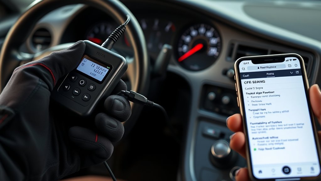
You’ll need an OBD‑II scanner that supports Toyota/JOBD2 or a jumper to bridge TE1 (TC) to E1. Locate the 16‑pin port under the driver’s dash, ignition OFF when you plug in, then turn ignition ON (engine off). Use the scanner for live codes or jump TE1–E1 and count long/short CEL flashes to decode DTCs. Record codes, check battery >11V, then diagnose or clear with a compatible tool — continue for step‑by‑step procedures and troubleshooting.
What You Need: Tools and Supra Model Compatibility
To read OBD-II codes on a Toyota Supra, start with the right scanner and confirm model compatibility: use an OBD-II scanner or code reader that supports JOBD2 and Toyota VVTi systems (1996 and later), since standard OBD-II tools may not connect correctly. You’ll verify OBD II Compatibility by checking the Supra’s year and VVTi designation, rejecting generic readers that lack JOBD2 support. Choose Scanner Features that include Toyota-specific protocols, live-data streaming, and persistent fault logging. You’ll prepare by charging the scanner, updating firmware, and reviewing the device manual. Connect only after confirming compatibility to avoid wasted time. If you want deeper control and freedom from dealership constraints, invest in Toyota-specialized diagnostic tools for expanded access and precise troubleshooting.
Locate the Supra OBD‑II Diagnostic Port and TE1/TC & E1 Pins
Locate the OBD‑II port under the dashboard on the driver’s side and expose the connector cover to reveal terminal labels. Identify the TE1/TC terminal (usually marked on the cover) and the E1 ground pin before attempting any bridging. Use a short jumper (wire or paperclip), confirm ignition is ON without starting the engine, then bridge TE1/TC to E1 to read the flashing codes.
Locating The Diagnostic Port
When you’re preparing to read codes on a Supra, you’ll typically find the 16-pin OBD-II connector tucked under the dashboard near the driver’s seat, often behind a removable cover that you should pry off or unclip for access. Locate the port visually, clear debris, and position yourself so you can access pins without straining. Use proper diagnostic tools and follow troubleshooting techniques to avoid electrical damage.
- Inspect under the dash and along the knee bolster for a rectangular cover.
- Remove the cover; expose the 16-pin connector and confirm orientation.
- Keep ignition OFF when plugging in adapters; prevent accidental shorts.
- Work in a liberated mindset: reclaim control of your car’s diagnostics with confidence.
Proceed methodically; accurate port location is the first step to effective diagnosis.
Identifying TE1/TC Pins
Start by seating yourself on the driver’s side and visually confirm the 16‑pin OBD‑II connector under the dash left of the steering column; you’ll then identify the TE1 (sometimes labeled TC) and E1 terminals—TE1 is the data pull-down pin used to trigger the ECU’s blink codes and E1 is chassis ground. With the ignition OFF, inspect the connector layout and locate the TE1 signal pin near the upper row and the E1 grounding pin on the lower row (positions vary by harness). Use a clean jumper or paperclip to bridge TE1 to E1 securely; make sure contact is solid to prevent false flashes. Turn the key to ON (engine off) and watch the check engine light flash; the blink sequence reveals stored DTCs.
Accessing E1 Ground Pin
Sit in the driver’s seat and pull down the Supra’s OBD‑II cover under the left side of the dash to expose the 16‑pin connector; you’ll be working with the TE1 (sometimes labeled TC) signal pin and the E1 chassis ground. Identify TE1 and E1 visually, then prepare a jumper (wire or paperclip) for grounding techniques. Turn the ignition to ON without starting the engine.
- Confirm E1 pinout against the connector diagram before touching terminals.
- Insert jumper between TE1 and E1 firmly to complete the circuit.
- Watch the Check Engine light for flash sequences; count long and short flashes.
- Remove jumper and key when finished to clear access state.
These steps free you to read stored codes safely and assert control over diagnostics.
Prepare the Car and Ignition for a Reliable Code Read
Before you read codes, get the car into a well-ventilated area and bring the engine to normal operating temperature so the ECU will provide valid data. You’ll verify engine readiness, battery voltage (>11 V), and basic sensor function before probing. Turn the ignition to ON (don’t start) to wake the ECU and illuminate the MIL. For VVTi models, bridge Tc and E1 at the diagnostic port per procedure. Use approved diagnostic tools and a multimeter; poor voltage or a bad TPS skews results. Follow steps systematically to keep control and avoid wasted time.
| Task | Check |
|---|---|
| Location | Ventilated area |
| Temp | Normal operating |
| Ignition | ON (no start) |
| Voltage | >11 V |
| Port | Bridge Tc–E1 (VVTi) |
Two Ways to Pull Codes: OBD‑II Scanner or Jump TE1/E1
You’ve got two reliable options to pull codes from a Toyota Supra: plug in an OBD‑II scanner to the diagnostic port for instant, readable fault codes and live data, or manually jump TE1 to E1 at the connector and read the MIL’s flash patterns with the ignition ON to capture stored codes. Use the method that enables you to act.
Two easy ways to pull Supra codes: plug in an OBD‑II scanner or jumper TE1–E1 and read MIL flashes.
- OBD II scanner advantages: plug-and-play, instant fault numbers, live stream, clear DTC definitions.
- Manual code retrieval: jumper TE1–E1, verify battery >11V, ignition ON, throttle closed.
- Read blinks sequentially from lowest code; long pauses mark code boundaries.
- Refer to the service manual to translate flash counts to specific DTCs.
Both routes empower you to diagnose, decide, and reclaim control.
Read Blink Codes Step‑By‑Step From the Check‑Engine Light
Locate the diagnostic port under the dash and bridge TE1 to E1 with a short wire or paper clip. Turn the key to ON (do not start) and watch the check‑engine light flash; record sequences of short and long flashes, where combinations like three short then one long mean code 31. Confirm battery voltage is above 11 V and the throttle valve is closed so the codes repeat cleanly between longer pauses for accurate interpretation.
Locate The Diagnostic Port
Start by crouching under the dashboard on the driver’s side—on a Toyota Supra the diagnostic (OBD-II) port sits near the steering column for easy access—so you can visually identify the connector and prepare to read codes. Locate the rectangular multi-pin socket; this is where diagnostic tools or a simple jumper connect to begin code interpretation. Confirm terminal labeling (TE1, E1) before proceeding.
- Clear space and illuminate the area for positive ID.
- Use a paperclip or jumper wire rated for low-voltage diagnostics.
- Keep ignition OFF while inserting the bridge to avoid shorts.
- Once located and bridged, turn ignition ON to initiate flash output.
This procedure empowers you to access fault data directly and reclaim control over vehicle diagnostics.
Interpret Blink Patterns
Once you bridge the Tc and E1 terminals and switch the ignition to ON (engine off), watch the check‑engine light for a series of blink‑pause patterns that encode stored trouble codes. Count blinks within each blink sequence: short repeated flashes form the digit groups, pauses separate digits, and longer pauses mark the end of a code. For example, three blinks, pause, one blink equals code 31. Record codes in order; multiple codes will repeat in the same cycle. You’ll use a code interpretation chart or online reference to map each sequence to its diagnostic meaning. Stay methodical: don’t guess, verify each blink pattern against the reference. Accurate code interpretation frees you to diagnose and act with confidence.
Interpret Common Toyota/Supra DTCs and Blink Patterns
When you’re reading Toyota/Supra DTCs from the Check Engine Light, interpret the blink sequence as two-digit codes: a single blink group gives the tens digit, a second blink group after a pause gives the ones digit (for example, three blinks, pause, one blink = code 31). Use Diagnostic Techniques that emphasize Code Interpretation and clear procedure.
- Read steady groups: first group = tens, second group = ones.
- Common code 42 = No.1 speed sensor fault; follow wiring and sensor checks.
- Misfire codes appear as separate entries; log each sequence for persistence.
- If flashes are uniform with no pause, no stored codes; erratic patterns imply connection issues.
You’ll liberate yourself from mystery by applying procedural checks, recording codes, and clearing only after verified repair.
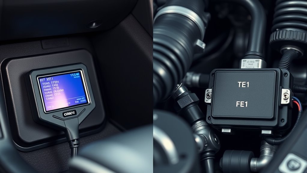
VVT‑i vs Older Supras: Pin Differences, TPS, Temp, and RPM Rules
Start by noting pinout differences: VVT‑i Supras use Tc–E1 for OBD‑II access while older Supras use TE1–E1, so you’ll wire the diagnostic port accordingly. Verify TPS calibration before reading codes—if you suspect TPS faults, unplug it and short the IDL pin to force an idle reference for troubleshooting. Finally, confirm coolant temperature and RPM meet the manufacturer’s thresholds for continuous fault detection on VVT‑i systems, since older models may flag or interpret faults under different conditions.
Pinout Differences Overview
Although both generations use the same rectangular diagnostic connector, VVT‑i Supras have a different pin layout than older models, so you must verify the exact terminal assignments for temperature, TPS and RPM before probing. You’ll confront pinout variations and diagnostic challenges; treat the connector as model‑specific. Confirm TC-to-E1 bridging on VVT‑i and consult manuals for non‑VVT‑i assignments.
- Verify model year pin map before touching terminals.
- Bridge only specified pins (e.g., TC and E1 on VVT‑i) to enter diagnostic mode.
- Identify TPS, coolant temp, and RPM pins using a wiring diagram, not guesswork.
- Avoid backprobing without power off; misconnections yield false codes.
Follow procedure, document the pin IDs, and free yourself from wasted troubleshooting time.
TPS Calibration Rules
If you’re calibrating the TPS, first confirm the diagnostic‑connector pinout for your Supra variant and hook the correct TPS, RPM and coolant‑temp terminals before proceeding. For VVT‑i models, use the specified pin configuration, ascertain the throttle valve is fully closed and battery voltage exceeds 11V; these TPS adjustment techniques prevent false OBD‑II readings. On older Supras, you can unplug the TPS and short the IDL pin to isolate calibration faults and verify adjustments after replacement. Throughout, monitor RPM and coolant temp inputs because the ECU uses those signals to validate TPS behavior. Treat Calibration importance as non‑negotiable: inaccurate TPS settings produce misleading fault codes and deny you clear diagnostic freedom. Follow procedures methodically to reclaim control.
Temp And RPM Thresholds
With TPS calibration confirmed, you’ll next verify the temperature and RPM conditions that allow the ECU to set and display codes — VVT‑i Supras enforce minimum coolant temperature and RPM windows before logging certain faults, while older Supras often will set codes over a broader range. You’ll reproduce those conditions to force accurate code capture: raise coolant to operating temp and hold RPM in the specified band.
- Check VVT i requirements: confirm coolant temp sensor reads within ECU-operating range.
- Hold RPM at the documented RPM thresholds for the target code (idle vs cruise).
- For older Supras, identify diagnostic connector pins before applying load or cranking.
- Re-run checks after TPS calibration to confirm repeatable faults.
Follow procedure; you’ll free the system to speak clearly.
Clearing Codes Safely : And When You Should Not Erase Faults
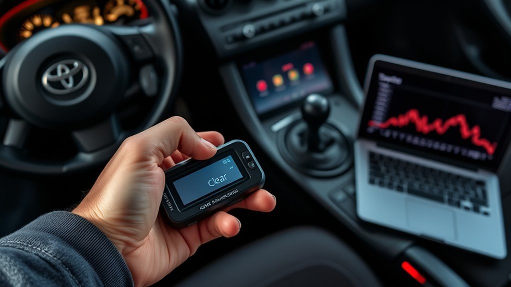
Before you erase any OBD-II codes, confirm you’ve fixed the root cause and understand the consequences of deleting stored faults. Follow code clearing precautions: document codes, repair the fault, then confirm fixes with a full drive cycle before erasing. Choose your diagnostic tool selection carefully — use a compatible OBD-II scanner that clears codes without resetting unrelated modules or adaptive learning unless you intend that. Don’t clear codes immediately after a fault; let the system complete readiness monitors so you won’t mask intermittent problems. Never erase codes tied to critical systems (engine, ABS, airbags) until you’re certain repairs are permanent, because deleting them can hide safety risks. After clearing, monitor the check engine light and re-scan to catch recurrence quickly.
Troubleshooting When Codes Won’t Read or Lights Flash Irregularly
When codes won’t read or the MIL flashes irregularly, start by confirming the ignition is set to ON (engine off) and the diagnostic connector under the dash is secure, because incorrect ignition status or a loose plug are the most common causes of failed or erratic reads. Check these procedural steps to regain control.
If codes fail or the MIL blinks, confirm ignition ON (engine off) and secure the under‑dash diagnostic connector first.
- Verify diagnostic connector issues: inspect pins, clean contacts, make certain of snug fit.
- Perform fuse troubleshooting: check the CEL/EFI-related fuse for continuity; replace as needed.
- Use a jumper wire to bridge TE1 and E1 per model-year procedure; confirm correct terminals before probing.
- If persistent, remove the EFI #1 fuse for a few minutes to reset the ECU, then retry code read.
You’ll act decisively, clearing communication faults so you can pursue true repairs.
Next Steps After Reading Codes: DIY Fixes, Parts, and When to See a Pro
After you pull codes, match each DTC to its specific fault—sensor, circuit, or system—so you can prioritize repairs and parts. Identify whether codes point to oxygen sensors, spark plugs, ignition coils, or wiring failures. For DIY repairs, use your vehicle’s repair manual, correct torque specs, and replacement part numbers. Isolate the faulty component, replace it, and clear codes with your scanner. Conduct a controlled test drive and re-scan; persistent faults or new codes signal deeper issues. If codes indicate transmission, intermittent wiring, or ECU faults, seek Professional advice and diagnostic services. You’re reclaiming control—repair what’s within skill and budget, document parts used, and escalate to pros when diagnostics exceed safe DIY scope.
Frequently Asked Questions
How to Read Toyota OBD-II Fault Code?
You plug an OBD II basics scanner into Toyota diagnostics port, turn ignition on, read codes, perform code interpretation, then use troubleshooting tips to liberate your ride from faults, follow procedural steps and repair resources.
How Do I Read My Toyota Engine Code?
Sure — you just don’t need mystical rites: plug an OBD-II scanner into the diagnostic port, turn ignition on, run engine diagnostics, retrieve codes, perform code interpretation, fix faults, clear codes, and free your car from ignorance.
Conclusion
You’ve got the tools and steps to read Supra OBD‑II codes—either with a scanner or by jumping TE1/E1—and you’ll know when to prep ignition, interpret blinks, or avoid clearing faults. Follow pin differences for VVT‑i vs older Supras, respect TPS/temp/RPM rules, and troubleshoot irregular reads methodically. If DIY limits are reached, get parts or a pro. Don’t be a VHS-era mechanic: document codes, verify fixes, and recheck before finalizing.