Your Tacoma’s oxygen (O2) and air‑fuel (A‑F) sensors monitor exhaust oxygen to control fuel trim and verify the catalytic converter; upstream O2s switch about 0.1–0.9V for closed‑loop feedback while A‑F sensors span 0–5V with higher voltage meaning leaner mixtures. Heaters bring sensors up to temp for accurate readings; heater faults set codes (e.g., P0135). If you see poor fuel economy, rough idle, or check‑engine lights, you can run quick voltage, wiring, and heater checks — more practical diagnostic and replacement details follow.
Who This Guide Is For and What You’ll Learn
If you own, maintain, or repair a Toyota Tacoma, this guide gives you the technical background and practical steps to understand oxygen sensor function, interpret sensor voltage (typically 0.1–0.9 V), distinguish standard O2 sensors from air–fuel ratio sensors, and apply diagnostics and safe removal/replacement practices for upstream and downstream units. You’re a Tacoma owner, mechanic, or DIYer seeking clarity: you’ll learn how sensors measure exhaust oxygen to quantify combustion efficiency and why accurate feedback prevents rich or lean conditions. The text focuses on actionable knowledge—how upstream sensors inform fuel trim, how downstream sensors verify catalytic performance, common failure modes, and implications for emissions and drivability. You’ll get stepwise diagnostic tools usage, voltage interpretation, and prioritized checks for sensor maintenance and replacement. Expect concise procedures for safe removal, contamination avoidance, connector handling, and torque. The tone empowers you to reclaim control over vehicle performance and emissions with technical, liberated confidence.
Toyota Tacoma O2/A‑F Sensor Locations
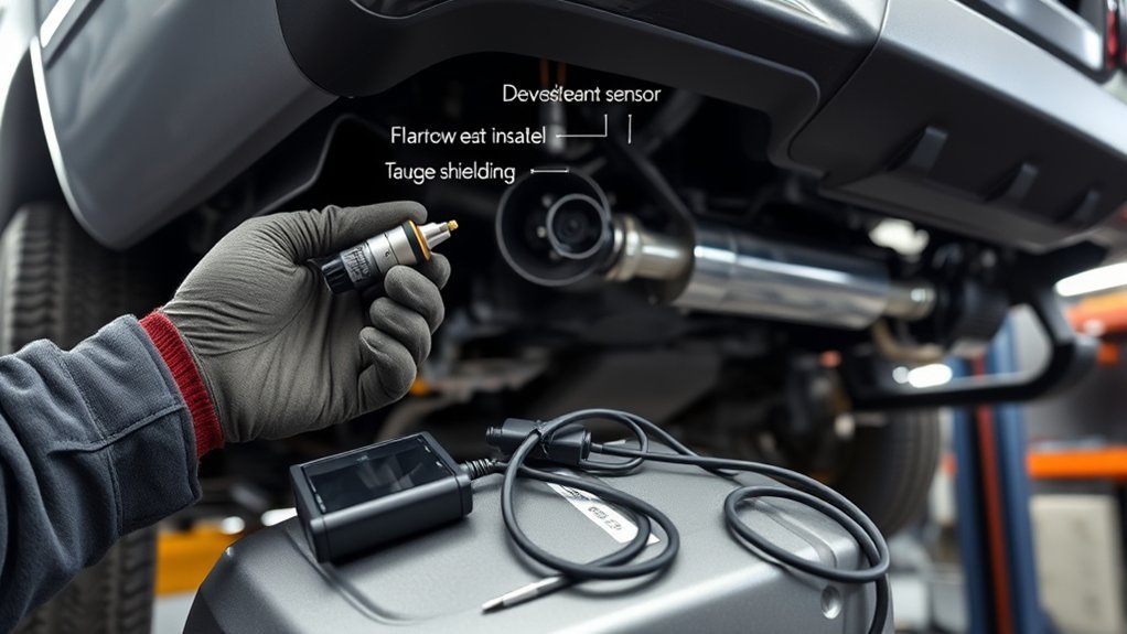
You’ll first identify bank 1 (contains cylinder 1) and bank 2 on V6 Tacomas to map each A‑F and O2 sensor. Note that upstream sensors sit before the catalytic converter and downstream sensors sit after it, with four‑cylinder models having only a single bank and pair of sensors. Finally, verify heater power/ground and signal wiring at each sensor—pinouts and routing can vary by model year, so check the service manual.
Bank Identification Locations
When identifying O2/A‑F sensor banks on a Toyota Tacoma, remember Bank 1 always contains cylinder one while Bank 2 (on V6 models) contains the remaining cylinders; four‑cylinder Tacomas only have a single bank. You’ll use sensor placement knowledge for targeted diagnostics and to claim control over maintenance decisions; this is about diagnostic importance and operational clarity.
- Locate Bank 1 first: follow the exhaust from cylinder one to find the upstream sensor; its placement dictates primary air‑fuel feedback and initial tuning.
- On V6 models, find Bank 2 sensors along the opposite exhaust runner; treat them as complementary inputs for balanced engine control.
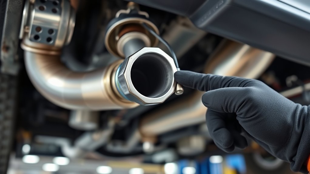
- Expect sensor access constraints—common tools (22mm wrench) and tight clearances—plan removal to minimize struggle and retain autonomy.
Upstream Vs Downstream
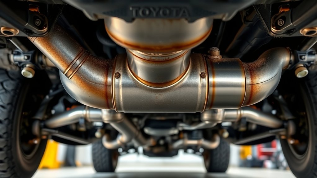
Although both types measure oxygen, you should distinguish upstream sensors (located before the catalytic converter) from downstream sensors (located after it) because they serve different control roles: upstream sensors provide real‑time air‑fuel feedback for closed‑loop fuel trim, while downstream sensors monitor catalytic converter efficiency and detect degradation. You’ll find upstream sensors on each bank feeding immediate voltage (≈0.1V lean to 0.9V rich) to the ECU to adjust injection. Downstream sensors sit post-catalyst to verify converter performance rather than trim fuel. In four‑cylinder Tacomas you’ll have one upstream and one downstream per bank; V6 models use two of each. For liberation-minded owners, prioritize sensor maintenance to preserve emissions control and engine response; track replacement frequency per mileage and symptom to avoid catalytic damage.
Sensor Heater Wiring
Because oxygen sensors need to reach operating temperature quickly, the Tacoma uses built‑in heaters with dedicated wiring to each upstream and downstream unit; you’ll rely on those heater circuits for accurate readings and prompt feedback to the ECM. Each sensor has two heater wires that the ECM controls, and faults in that wiring produce diagnostic codes and degraded emissions control.
- Inspect: check connectors, pins, and harness for corrosion or breaks; prioritize sensor maintenance to prevent misreads.
- Test: verify heater resistance and power signal at both upstream and downstream sensors before replacing sensors.
- Repair: perform wiring repairs with heat‑shrink, proper terminals, and routing away from exhaust heat to restore function and preserve your vehicle’s autonomy.
Cold Start and Open‑Loop vs Closed‑Loop Behavior
During a cold start, your Tacoma runs in open‑loop mode and ignores oxygen sensor feedback, relying on preprogrammed, enriched fueling to guarantee reliable ignition and faster catalyst warm‑up. You face cold start challenges: poor vaporization, higher friction, and emissions risk. Open loop advantages include predictable enrichment and faster heater-driven sensor warm-up, preventing misfires while the catalytic converter reaches operating temperature.
As temperatures rise and the sensor attains its operating threshold, the PCM switches to closed‑loop operation. You then get real‑time feedback from the heated oxygen sensor, allowing the PCM to modulate injector pulse width to converge on the stoichiometric 14.7:1 ratio. This change is conditional on both sensor and catalyst temperature and restores adaptive control for fuel trim corrections. The closed‑loop regime continuously corrects lean/rich deviations, improving fuel economy and cutting emissions. You rely on this thermal-dependent sequence to balance drivability, regulatory compliance, and the long-term health of the exhaust aftertreatment system.
Reading Voltages: Interpreting Lean vs Rich (Tacoma Sensors)
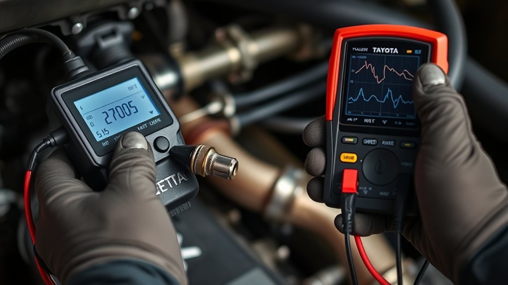
You’ll read oxygen sensor voltages from about 0.1 V (lean) to 0.9 V (rich) on pre-catalyst O2 sensors, while AFR sensors sit near 3.3 V within a 0–5 V span where higher = lean and lower = rich. Watch the oscillation of O2 sensors for proper closed‑loop switching and use AFR sensor steadier output for fine fuel trim. Remember sensor heater status affects readings timing—cold sensors lag and can falsely show lean until the heater brings them to operating temperature.
Voltage Ranges Explained
When you read oxygen sensor voltages on a Tacoma, low readings around 0.1 V indicate a lean mixture while highs near 0.9 V show rich combustion, whereas air–fuel ratio (wideband) sensors output 0–5 V with higher voltages corresponding to leaner conditions. You’ll use those ranges to judge sensor calibration and spot voltage fluctuations that signal faults. Upstream sensors drive closed‑loop control; downstream ones verify catalytic performance. ACRONYM: interpret quickly, act decisively.
- Monitor: expect narrowband 0.1–0.9 V oscillation; wideband ≈3.3 V at stoichiometry, higher when lean.
- Diagnose: erratic swings beyond normal frequency suggest sensor degradation or wiring issues.
- Adjust: confirm sensor calibration before replacing parts to preserve freedom from unnecessary repairs.
Lean Vs Rich Signals
Although the narrowband oxygen sensor in your Tacoma swings between about 0.1 V for lean and 0.9 V for rich, you should read those voltages as a binary indicator of combustion rather than an absolute AFR, while the wideband (AFR) sensor uses a higher-voltage scale—around 3.3 V at stoichiometry and higher when lean—to provide precise air–fuel ratio data. You monitor oscillation patterns with diagnostic tools to detect persistent lean or rich conditions, which affect emissions, fuel economy, and sensor lifespan. Interpret narrowband as switch-like; use wideband for tuning or troubleshooting. Replace sensors showing slow response or amplitude loss. Liberation comes from empowered diagnostics and timely maintenance.
| Signal | Narrowband | Wideband |
|---|---|---|
| Lean | ~0.1 V | >3.3 V |
| Rich | ~0.9 V | ~0 V |
Heater Influence On Readings
Because the heater brings the sensor to operating temperature quickly, you’ll see accurate narrowband voltages (about 0.1 V lean to 0.9 V rich) and wideband outputs (higher volts = lean, lower = rich) much sooner after startup; this shortens open-loop duration and lets the ECU correct mixture promptly. You’ll monitor oscillation patterns to verify heater efficiency and detect faults that delay valid readings. A failing heater produces sluggish or absent swings, causing prolonged rich running and higher emissions, undermining sensor longevity and your control over the engine.
- Check heater current and response time to confirm rapid warm-up and consistent narrowband oscillation.
- Use wideband voltage trends to spot delayed stabilization or stuck readings.
- Replace heaters proactively to protect sensor longevity and emissions freedom.
Symptoms, Heater Codes, and 5 Quick Diagnostics
If your Tacoma shows poor fuel economy, a rough idle, higher emissions, or an illuminated check engine light with O2-related codes, those are classic signs the oxygen sensor’s performance is degrading. You’ll use symptom identification to isolate failures: CEL codes and drivability changes point to sensor or heater function problems. Heater codes like P0135/P0141 flag the heater circuit; without heater operation the sensor won’t reach operating temp and gives inaccurate readings.
| Quick Check | Action |
|---|---|
| Scan codes | Read OBD-II for O2/heater codes |
| Visual | Inspect wiring, connectors, exhaust leaks |
Five quick diagnostics: 1) Read and record trouble codes. 2) Visually inspect sensor harness and connector for corrosion or breaks. 3) Check for exhaust leaks near the sensor. 4) Measure sensor voltage (0.1–0.9 V) while warm. 5) Test heater circuit resistance/current per service spec. If a sensor’s seized, a 22mm wrench and penetrating fluid often free it.
Replace It Yourself? When to DIY vs Call a Shop
When you’ve confirmed O2 or heater fault codes and have a 22mm wrench on hand, replacing the sensor is a straightforward, one- or two-hour job for anyone with basic mechanical skills and a jack or ramps. You’ll save labor costs and gain control over maintenance, but weigh parts quality and sensor longevity before committing.
- DIY advantages: lower cost comparison favoring parts-only expense, direct inspection, and immediate replacement. You control part choice—opt for OEM to protect sensor longevity and emissions performance.
- Call a shop when: the sensor is inaccessible, codes suggest upstream issues, you lack lifts or diagnostic tools, or previous removal attempts failed. Shops handle seized sensors and advanced verification.
- Risk management: if you value liberation through self-service but face uncertain diagnostics or limited tools, buy OEM parts and proceed; otherwise, outsource to avoid repeat failures and hidden repair costs.
Practical Replacement Tips: Tools, Socket Sizes, and Stuck‑Sensor Tricks
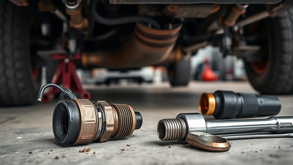
Now that you’ve weighed DIY versus a shop, get specific about the gear and tactics that make the job predictable. You’ll need a 22mm oxygen sensor wrench or a 22mm open-end/box wrench; that size fits Toyota Tacoma sensors for straightforward removal. Carry penetrating oil and a shop rag; for sensors seized in the manifold, apply brake fluid to the threads to penetrate corrosion, wait, then back the sensor out slowly. Check for heater codes before replacement—heater failures alter the rich/lean cycle and can mislead diagnosis. Remove protective caps from new sensors prior to install to avoid damage and guarantee proper function. Torque new sensors to factory spec; over-tightening risks thread damage. When choosing parts, weigh sensor maintenance tips against aftermarket concerns: aftermarket sensors may reduce reliability or introduce faults compared with OEM. If threads strip or the sensor won’t budge, stop and consult a shop to avoid catastrophic manifold damage—liberate yourself wisely.
Frequently Asked Questions
What Is the Main Function of an Oxygen Sensor?
The main function is to measure exhaust oxygen so your ECU adjusts fuel injection for ideal combustion; you’ll learn oxygen sensor types and sensor maintenance to preserve efficiency, emissions control, and your vehicle’s performance and autonomy.
What Is the Work of an Oxygen Sensor in a Toyota Car?
You monitor Oxygen sensor types and Sensor location: you use upstream and downstream sensors to measure exhaust oxygen, feed voltage signals to the ECU, adjust air-fuel ratio for efficiency and emissions, and guarantee catalytic converter performance.
What Should Oxygen Sensors Read at Idle?
Like a heartbeat, idle readings should swing between about 0.1V and 0.9V rapidly; you’ll want sensor calibration confirming continual oscillation, so the ECU can freely tune air-fuel balance for efficient, liberated engine performance.
Conclusion
Think of your Tacoma’s O2 sensors as a pair of gardeners: one scouts the soil at the root (upstream) and one checks the harvest (downstream). When they send steady, accurate signals your engine breathes clean and efficient; when they falter, symptoms sprout. Use the diagnostics here like pruning tools—measure voltages, watch heater codes, replace stubborn sensors with the right sockets—and you’ll restore balance before small issues become a thicket of costly repairs.