If your Toyota Tundra ABS light comes on, start with simple checks: confirm brake lights work, test the brake‑light switch, and inspect the 15A STOP and 7.5A ECU‑IG No.1 fuses. Use an OBD2 ABS scanner and multimeter to read codes, monitor wheel‑speed sensor voltages and resistances, and compare wheel speeds for symmetry. Clean connectors, verify grounds, and swap suspect sensors. Replace inexpensive parts first; continue below for detailed step‑by‑step diagnostics and fixes.
Toyota Tundra ABS: Quick Checks First (Brake Lights, Fuses, Switch)
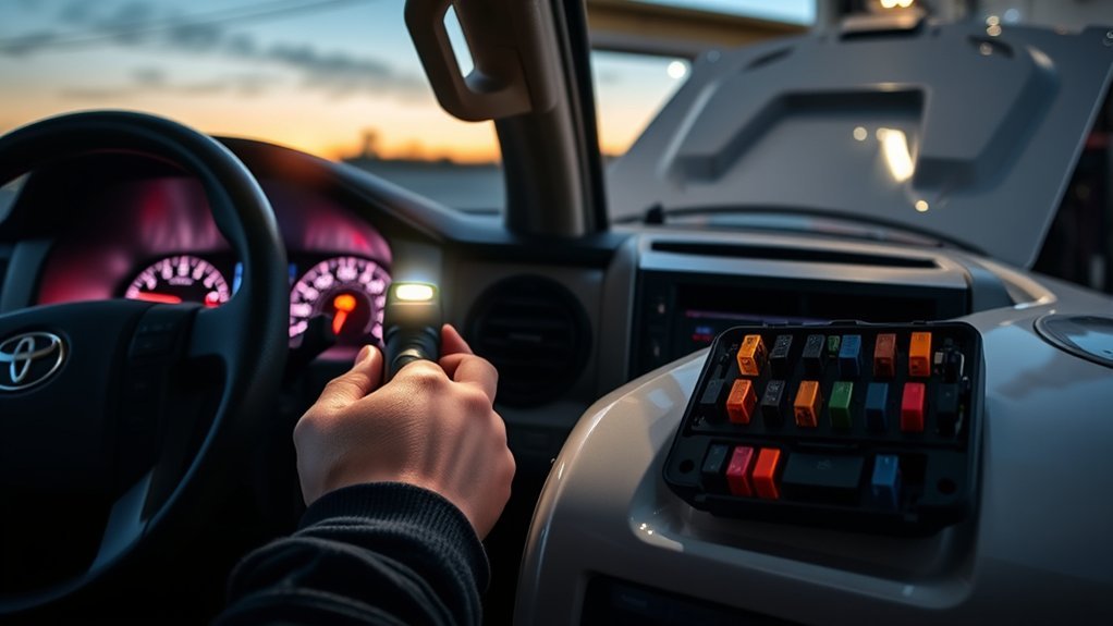
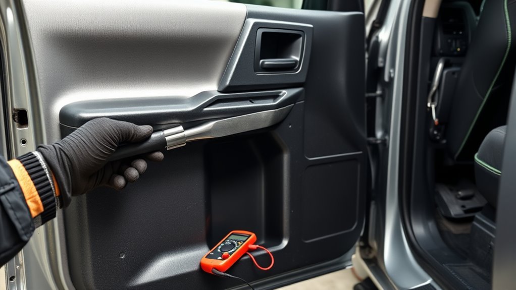
Before diving into deeper diagnostics, start with a few quick checks you can do in minutes: confirm the brake lights work (a failed brake light switch often triggers the ABS warning), inspect the ABS-related fuses—especially the 15A “STOP” and 7.5A “ECU-IG No.1″—and test the brake light switch by actuating it several times while watching the ABS lamp. You’ll perform brake light troubleshooting first: have an assistant press the pedal or use a reflective surface to verify bulb illumination and note any intermittent behavior. Next, do a targeted fuse inspection; remove and visually inspect the two fuses for continuity or signs of heat damage, and replace with OEM-rated parts if needed. Manually actuate the brake light switch multiple times while observing the ABS lamp to catch marginal switch faults. Check switch wiring and connectors for tightness and corrosion, cleaning contacts as required. If faults persist after these steps, consider a system reset via battery disconnect before escalating diagnostics.
Step‑By‑Step Diagnostic Checklist: Tools & Live Data to Collect
You’ll need a compatible OBD2 scanner that reads ABS codes and live data plus a multimeter, basic hand tools, and wire‑backprobe leads to collect accurate readings. Capture live data for wheel speed sensors (each wheel), ABS module status, vehicle speed, and brake pedal switch state while comparing sensor resistances with a multimeter (expect ~0.1–0.2 ohm for functional sensors). Record codes and monitor the system after any repair to confirm the fault doesn’t recur.
Required Diagnostic Tools
When diagnosing a Tundra ABS light, gather the right diagnostic tools so you can quickly identify sensor faults and wiring issues: an OBD2 scanner capable of reading ABS codes and live data, a multimeter for resistance checks (speed sensors typically measure ~0.1–0.2 Ω), and a Bluetooth OBD2 reader if you want portable live-data access (roughly $100). You’ll want tools that prioritize sensor compatibility and diagnostic efficiency so you can liberate yourself from guesswork.
- OBD2 scanner (ABS code + live data)
- Digital multimeter (resistance and continuity)
- Bluetooth OBD2 adapter (portable live-data on phone)
- Electrical cleaning kit (contact cleaner, brushes, scrapers)
Inspect connectors for green corrosion, verify sensor ohms, and keep connectors clean to restore reliable signals.
Live Data Parameters
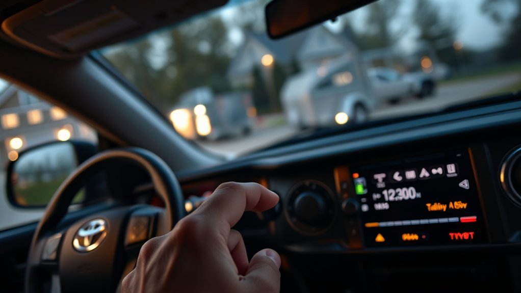
Start by connecting a capable OBD2 scanner and selecting ABS live-data mode so you can monitor each wheel speed sensor, sensor voltages, and calculated vehicle speed in real time. You’ll perform live data analysis to spot mismatches, voltage drops, or open circuits. Note resistance values (typical ~0.1–0.2 ohms) and record during a test drive to reveal intermittent faults. Compare wheel speeds for symmetry; a single deviating sensor often triggers the ABS light. Verify module responses under varied speeds to confirm sensor calibration and ABS logic. Log files for later review and liberation from guesswork.
| Parameter | Normal Range | Action if Outside |
|---|---|---|
| Voltage | 0.0–5.0 V | Inspect wiring/sensor |
| Resistance | 0.1–0.2 Ω | Replace sensor |
| Wheel speed | Equal | Record/test drive |
How ABS, Traction Control & Shift‑Lock Interact : Circuits to Check
Because these systems share sensors, switches, and power feeds, a fault in one often shows up as warnings for the others—so you need to trace the common circuits methodically. You’ll map ABS interaction with traction control and the shift lock mechanism, focusing on shared inputs and power paths. Prioritize the brake light switch, the stop and ECU fuses, and the main harness connections.
- Check fuses: verify the 15A stop and 7.5A ECU-IG No.1 fuses; a blown fuse causes system malfunctions.
- Brake light switch: test for proper signal continuity and correct plunger operation; replacements restore safety features.
- Wiring inspection: follow harnesses from wheel sensors and ABS module; look for corrosion, chafing, and loose connectors.
- Module power/grounds: confirm constant and switched feeds to ABS/ECU and solid ground returns.
Work methodically, isolate circuits, and free yourself from repeat failures by fixing root electrical faults first.
Test Wheel Speed Sensors: Multimeter & Oscilloscope Tips
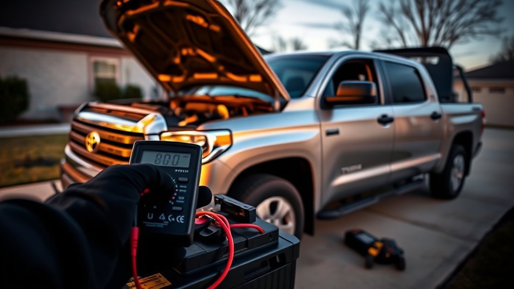
Start by measuring the sensor resistance with a multimeter—functional wheel speed sensors typically read about 0.1–0.2 ohms, while an open or megaohm reading means replacement. Then perform a dynamic test with an oscilloscope and view the sensor waveform while the wheel spins to confirm clean, consistent pulses. Before testing or replacing, clean corroded connections (green tint) and inspect the mounting area for rust or debris to guarantee proper contact and alignment.
Measure Resistance With Multimeter
Before you disconnect the sensor, set your multimeter to the low-ohms range and verify its lead condition so you get accurate readings; then unplug the wheel speed sensor connector and measure resistance across the sensor terminals. You’re doing sensor maintenance and confirming wiring integrity—readings around 0.1–0.2 ohms indicate a good sensor. If you see megaohms or “OL,” you’ve likely got an open circuit or broken wiring.
- Inspect connectors for corrosion—green tint equals oxidation that reduces conductivity.
- Verify wires aren’t shorted together before testing; shorts mask true resistance.
- Compare high readings to a known-good sensor to confirm failure.
- Remove sensors cautiously in rust-prone areas to avoid breakage and preserve liberation through competent repairs.
View Waveforms With Oscilloscope
After you’ve checked resistance with a multimeter, hook an oscilloscope to the wheel speed sensor to observe its signal waveform in real time. Set probe attenuation, time base, and trigger in your oscilloscope settings to capture low-frequency sine waves; use a ground reference and appropriate voltage scale. Record several revolutions while the wheel spins slowly. A healthy sensor yields a clean sine wave; compare that waveform analysis to a known-good sensor to spot amplitude drop, distortion, erratic spikes, or a flat line indicating no signal. Inspect and clean connectors before condemning the sensor—corrosion masks true behavior. Document readings and save waveforms for verification. Use methodical tests so you free yourself from guesswork and make targeted repairs.
Check the ABS Module, Connectors, and Grounds for Corrosion/Moisture
When diagnosing ABS warnings, inspect the ABS module connectors and nearby grounds for corrosion or moisture intrusion, since compromised contacts or poor grounding will produce intermittent faults and trigger the light. Perform a targeted corrosion inspection and moisture prevention check: remove the connector covers, look for green/white deposits, and verify pin geometry and contact integrity.
- Visually inspect connector pins and sockets for rust, pitting, or discoloration; bent pins cause intermittent signals.
- Clean affected contacts with an electrical cleaner; dry thoroughly and reseat to restore metal-to-metal contact.
- Trace and test main ground points near the rear axle and along the chassis for tightness and continuity; poor grounds mimic sensor faults.
- Reapply dielectric grease after cleaning to repel moisture and support long-term moisture prevention.
Be methodical: document findings, test continuity with a multimeter, and recheck ABS codes after repairs to confirm the warning clears.
Common DIY Fixes and Expected Costs (Switches, Sensors, Harnesses)
Start by targeting the inexpensive, high-probability fixes you can tackle with basic tools and a multimeter: brake light switch replacement ($20–$40), wheel speed sensor swaps ($30–$100 each), fuse and connector checks (<$10), and harness cleaning/repair. You’ll verify switch continuity at the pedal, swap a suspect wheel speed sensor, and inspect the wiring harness for chafing or corrosion. Clean connectors with contact cleaner and apply dielectric grease to resist moisture. Track parts and labor as you go; replacing an ABS control module is costly ($200–$600) if these fail.
| Item | Typical DIY Action |
|---|---|
| Brake light switch | Test continuity, replace ($20–$40) |
| Wheel speed sensor | Swap/test sensor ($30–$100) |
| Fuse/connector | Inspect/replace (<$10) |
| Wiring harness | Clean, repair damaged sections |
Work methodically, document tests, and prioritize fixes that restore freedom from avoidable shop bills.
When to DIY vs. Call a Pro : What Diagnostic Data to Bring
Curious whether to tackle the ABS light yourself or call a pro? You should base that decision on diagnostic importance and the data you can gather. Use an OBD2 scanner that reads ABS codes; clear, specific codes often let you DIY basic sensor or fuse fixes. If codes implicate the ABS control module or complex wiring, seek a professional assessment.
Bring this concise packet to the shop:
Bring a concise packet to the shop: ABS codes, related warnings, recent repairs, and your simple check results.
- Scanned ABS codes and freeze-frame data — tells the tech where to start.
- Notes on other warnings (traction control, VSC) — flags possible system-wide faults.
- Records of recent repairs or part swaps (wheel sensors, modules) — prevents redundant work.
- Results of simple checks you performed (fuses, connector corrosion) — saves diagnostic time.
You want autonomy, so perform what’s safe and reversible. If issues persist or codes point to module or wiring integrity, hand it to a pro for definitive testing and repair.
Final Troubleshooting Flowchart: Next Steps Based on Test Results
If your visual and multimeter checks pinpoint a bad wheel-speed sensor, replace that sensor first and recheck resistance and connector integrity before moving on; otherwise, proceed to inspect all ABS-module wiring and grounds for corrosion or loose pins, clear stored fault codes, and perform a controlled test drive to confirm whether the ABS light returns. Start the final troubleshooting flowchart by confirming each sensor’s resistance: 0.1–0.2 ohms indicates intact wiring; megaohm readings indicate an open circuit needing replacement. After sensor swap, verify connector seating and corrosion-free contacts. If the light persists, trace harnesses to the ABS module, probing for continuity and poor grounds. Repair or re-pin any corroded terminals, then clear codes with a scanner. Use a short, controlled road test with braking events to force ABS self-checks. If faults recur, escalate to module bench testing or professional reprogramming. These diagnostic strategies give you a clear, liberated path to resolve the ABS warning.
Frequently Asked Questions
Why Is My ABS Light on in My Toyota Tundra?
Your ABS light’s on because the ABS system detected a sensor malfunction or wiring corrosion causing brake issues; use diagnostic tools to read codes, follow maintenance tips, and you’ll regain control and freedom on the road.
Conclusion
You’ve got a clear, methodical path: start with the basics (brake lights, fuses, pedal switch), collect live data and wheel‑speed readings, then inspect sensors, wiring, grounds and the ABS module. If you find a faulty sensor, corroded connector, or bad ground you can often fix it yourself; complex module failures merit a shop. Example: one owner traced an intermittent ABS light to a pinched harness at the left front wheel—repaired the harness and cleared codes in under an hour.