Last updated: July 31, 2026 · By: Editorial Team
How this guide was prepared: This guide combines Toyota service information for the 2TR-FE engine, DENSO sensor-installation guidance, EPA readiness guidance, and cross-generation fitment checks. It does not claim that one torque value, connector, access route, or mounting style fits every 4-cylinder Tacoma.
What’s in This Article
- Which 4-Cylinder Tacoma Procedure Applies?
- What This Repair Fixes and How Hard It Is
- How to Disconnect the Upstream Sensor Wiring
- How to Remove the Old Upstream Sensor
- How to Install a Threaded or Flange-Mounted Sensor
- How to Route and Reconnect the Harness
- How to Test the Repair and Troubleshoot a Returning Light
- Frequently Asked Questions
To replace the upstream O2 sensor on a 4-cylinder Toyota Tacoma, first separate the truck by model year and engine. The upstream unit is Bank 1 Sensor 1, but Toyota may identify it as an air-fuel ratio or A/F sensor. Older first-generation trucks may use a two-fastener flange, many 2005–2023 2.7L applications use a threaded A/F sensor, and the redesigned 2024–2026 Tacoma uses a different 2.4L turbo platform. Confirm the VIN, engine, emissions certification, connector, wire length, and visible mounting style before loosening anything.
Toyota introduced the turbocharged 2.4L four-cylinder and available i-FORCE MAX hybrid powertrain with the fourth-generation Tacoma. Do not apply an older 2TR-FE or flange-sensor procedure to a 2024 or newer truck without checking its VIN-specific service information. See Toyota’s fourth-generation Tacoma powertrain overview.
Quick Answer
Turn the ignition off, let the exhaust cool, save the diagnostic code and freeze-frame data, and identify the truck’s model year, engine, emissions package, and sensor mount. Inspect the connector, heater circuit, and exhaust for faults before ordering a sensor. Unplug and free the harness, remove either the threaded sensor or the two-fastener flange, install the exact VIN-matched part with the correct seal and model-specific torque, restore the factory wire route, then check for exhaust leaks, returning codes, and readiness-monitor status.
Key Takeaways
- Do not order a sensor from the phrase “4-cylinder Tacoma” alone; match the VIN, engine, emissions certification, connector, wire length, and mounting design.
- Do not assume a 2024–2026 turbo or hybrid Tacoma uses the same procedure as a 2005–2023 2.7L 2TR-FE truck.
- Identify whether the sensor is threaded or flange-mounted before choosing tools, a gasket, or a torque specification.
- A trouble code names a circuit or operating condition; it does not automatically prove the sensor itself has failed.
- Do not use an open flame around the engine bay or exhaust system to free seized hardware.
- Record codes before clearing them, protect the harness from heat, and verify the repair with a leak check, rescan, and readiness check.
Before You Start: Which 4-Cylinder Tacoma Procedure Applies?
Start with the model year, VIN, engine code, emissions label, and code stored in the engine computer. “Upstream O2 sensor” is a useful search term, but the catalog or service manual may call the part an air-fuel ratio sensor. A code can identify a sensor-related circuit or operating condition, but it does not prove that the sensing element has failed.
| Tacoma application | Main identification issue | What to verify before removal |
|---|---|---|
| 1995–2004 2.4L or 2.7L | O2/A/F terminology, emissions calibration, and flange or threaded hardware can vary | Visible mount, transmission, emissions label, connector, wire length, gasket, and fastener torque |
| 2005–2023 2.7L 2TR-FE | Toyota commonly identifies Bank 1 Sensor 1 as an A/F sensor; verified service examples use a threaded sensor | Exact year, drivetrain, emissions calibration, service-manual torque, connector, and harness route |
| 2024–2026 2.4L turbo or i-FORCE MAX | New engine and exhaust architecture; older 2TR-FE instructions may not apply | VIN-specific Toyota service information and the exact gas or hybrid application |
Inspect the connector, harness, nearby exhaust joints, and related fuses before replacing the part. Look for a loose or corroded connector, rubbed insulation, melted loom, a blown heater-circuit fuse, or soot around a leaking joint.
Emissions certification is not a formality: California and other CARB-aligned states require a sensor certified for that specific calibration, while a 49-state federal truck of the same year and engine uses a different certified part even when the connector and wire length look identical. Installing the wrong certification can trigger a code, or cause an emissions-inspection failure, even though the sensor physically fits. Confirm the vehicle’s emissions label before ordering.
Gather an OBD-II scan tool, safety glasses, gloves, a small pick, penetrating oil, and a torque wrench. Then add the tools for the mounting style you can see on the truck.
- Threaded sensor: use the correctly sized slotted O2-sensor socket, six-point flare-style wrench, or other service-approved tool that fully engages the sensor hex.
- Flange-mounted sensor: use the correctly sized socket for the two flange fasteners and obtain the specified new gasket.
- Replacement part: match the connector, wire length, mounting design, engine, transmission where applicable, and emissions calibration.
- Retainers: have replacement clips ready if an aged plastic retainer breaks.
DENSO’s installation guidance recommends disconnecting the lead and freeing it from its retainers before turning the sensor, hand-starting a threaded replacement, using a new gasket on a flange design, and restoring the original wire route. See DENSO’s lambda-sensor installation guidance.
Warning: Work only on a fully cooled exhaust. If you must raise the truck, support it on rated jack stands on a firm, level surface. Never rely on a jack alone, and do not use an open flame to loosen the sensor or fasteners.
Switch the ignition off and keep the key away from the truck. Follow the model-specific service procedure for battery disconnection. Some Toyota procedures instruct technicians to disconnect the negative terminal, but doing so can erase learned values and reset OBD readiness monitors.
Before removal, compare the new and old parts while the old sensor is still installed. Confirm the connector shape, terminal count, wire length, heat shielding, sensor body, mounting style, and gasket requirement.
What Does the Upstream Sensor Do, and Is Replacement the Right Fix?
The upstream sensor reports exhaust oxygen to the engine control unit so it can correct the air-fuel mixture. Bosch describes the lambda sensor as the feedback device that lets the control unit regulate injected fuel for efficient combustion and emissions control. You can read the manufacturer’s overview in Bosch’s lambda-sensor history and function guide.
Replacement is appropriate only after the stored code, wiring inspection, exhaust-leak check, heater-circuit checks, and available live data point to the sensor. A damaged connector, rubbed wire, blown heater fuse, failed relay, intake leak, fuel-control fault, or exhaust leak can produce similar symptoms.
What Problems Can a Confirmed Bad Upstream Sensor Cause?
A confirmed faulty upstream sensor can contribute to incorrect fuel-trim feedback, poor fuel economy, rough running, higher emissions, and a check engine light. Replacing the failed part restores a usable signal, but it will not repair unrelated fuel, ignition, intake, wiring, or exhaust faults.
Use this diagnosis gate before buying a sensor:
- Record the evidence: save the stored and pending codes plus freeze-frame data before clearing anything.
- Identify the code type: determine whether it describes a heater circuit, signal performance, an open or short, a system-wide lean or rich condition, or catalyst efficiency.
- Inspect the circuit: check the connector, harness, heater power, ground, relay, and related fuse information for your model.
- Check for leaks: inspect the intake system and the exhaust manifold or joints ahead of the sensor for leaks, soot, or abnormal noise.
- Review live data: use the correct Toyota A/F-sensor data interpretation rather than applying a generic narrowband 0.1-to-0.9-volt test to every upstream sensor.
- Confirm the part: match the VIN, engine, transmission where applicable, emissions package, connector, wire length, and mount before opening the replacement.
Which Trouble Codes Can Point Toward Bank 1 Sensor 1?
The exact code set varies by model year and engine. The following examples show why the code must guide a test rather than become an automatic parts order. Toyota’s 2TR-FE diagnostic information identifies P0031/P0032 as upstream A/F heater-control codes and treats P2195/P2196 and P2237–P2253 as separate signal or circuit diagnoses.
| Example code or family | What it describes | First checks |
|---|---|---|
| P0031 or P0032 | Bank 1 Sensor 1 A/F heater-control circuit low or high on applicable 2TR-FE systems | Heater resistance, fuse, relay, power supply, connector, harness, and ECM control circuit |
| P2195 or P2196 | Bank 1 Sensor 1 signal biased or stuck lean or rich | Intake leaks, exhaust leaks, fuel delivery, sensor response, wiring, and related codes |
| P2237–P2239 or P2252–P2253 | A/F sensor pumping-current circuit open, short, or abnormal response | Connector terminals, harness continuity, shorts, sensor circuit, and service-manual test sequence |
| P0171 or P0172 | System too lean or too rich; not proof of a failed sensor | Intake leaks, MAF data, fuel pressure, injectors, ignition, exhaust leaks, and fuel trims |
| P0420 | Catalyst-system efficiency below threshold; not an automatic upstream-sensor diagnosis | Exhaust leaks, misfires, fuel control, oil or coolant contamination, upstream/downstream data, and converter condition |
An air-fuel ratio sensor does not report data the same way a narrowband oxygen sensor does. A narrowband O2 sensor produces a switching voltage that swings roughly between 0.1 and 0.9 volts as the mixture cycles rich and lean. A wideband A/F sensor instead outputs a variable pumping current, which a scan tool converts into a lambda or air-fuel ratio value, and it tends to hold closer to a steady target rather than sweeping high and low like a narrowband signal. Reading A/F sensor data with the expectations built for a narrowband sensor is a common misdiagnosis — confirm the scan tool is displaying the correct A/F or lambda parameter for the vehicle rather than watching for narrowband-style switching.
If the diagnosis remains uncertain, test the circuit with model-specific service information instead of replacing parts by code alone.
How Difficult Is Upstream Sensor Replacement?
This is a moderate DIY repair when the connector is accessible and the exhaust hardware is not seized. The time cannot be generalized across every 1995–2026 four-cylinder Tacoma because corrosion, flange hardware, engine-bay access, damaged threads, heat shields, and brittle connectors can change the job substantially.
Stop if the sensor hex begins to round, a flange stud starts to turn, a nut deforms, or the threads bind during removal. Repairing a damaged exhaust bung or broken stud requires more tools and experience than replacing the sensor.
How Can You Tell Whether the Sensor Is Threaded or Flange-Mounted?
Look at the point where the sensor meets the exhaust before loosening anything. A threaded sensor has a hex-shaped body that screws directly into a bung. A flange-mounted sensor sits on a flat plate held by two fasteners and normally seals with a separate gasket.
| Mounting style | What you will see | Removal method | Seal |
|---|---|---|---|
| Threaded | Sensor hex screwed into an exhaust bung | Slotted sensor socket, six-point flare-style tool, or correctly sized service-approved wrench | Follow the replacement-part instructions; no separate flange gasket unless specified |
| Flange-mounted | Flat sensor plate with two fasteners | Correct socket for the flange nuts or bolts | New specified exhaust gasket |
Do not force a threaded-sensor procedure onto a flange-mounted part, or vice versa. The tools, sealing method, fastener risks, and tightening sequence are different.
How Do You Disconnect the Upstream O2 Sensor Wiring Safely?
Trace the sensor lead from the exhaust to its connector before loosening the sensor. Note every clip, bracket, heat shield, and bend so you can restore the original routing.
Press the connector lock with your fingers or a small pick, then pull on the connector housings rather than the wires. If the lock will not move, clean away dirt and confirm the direction of the tab before applying more force.
Release the harness from its retainers one at a time. Retainer locations vary by model, so do not pull the lead toward a guessed bracket, hose, or transmission line.
| Task | What to check |
|---|---|
| Trace wiring | Photograph the complete factory route |
| Release connector | Pull the housings, not the wires |
| Inspect pins | Look for corrosion, heat damage, bent pins, or pushed-back terminals |
| Remove retainers | Preserve clips and note their orientation |
| Protect the plug | Keep dirt, oil, anti-seize, and penetrating fluid out of the connector |
Once disconnected, position the harness where it cannot be pinched, melted, contaminated, or pulled while you remove the sensor.
How Do You Remove the Old Upstream O2 Sensor?
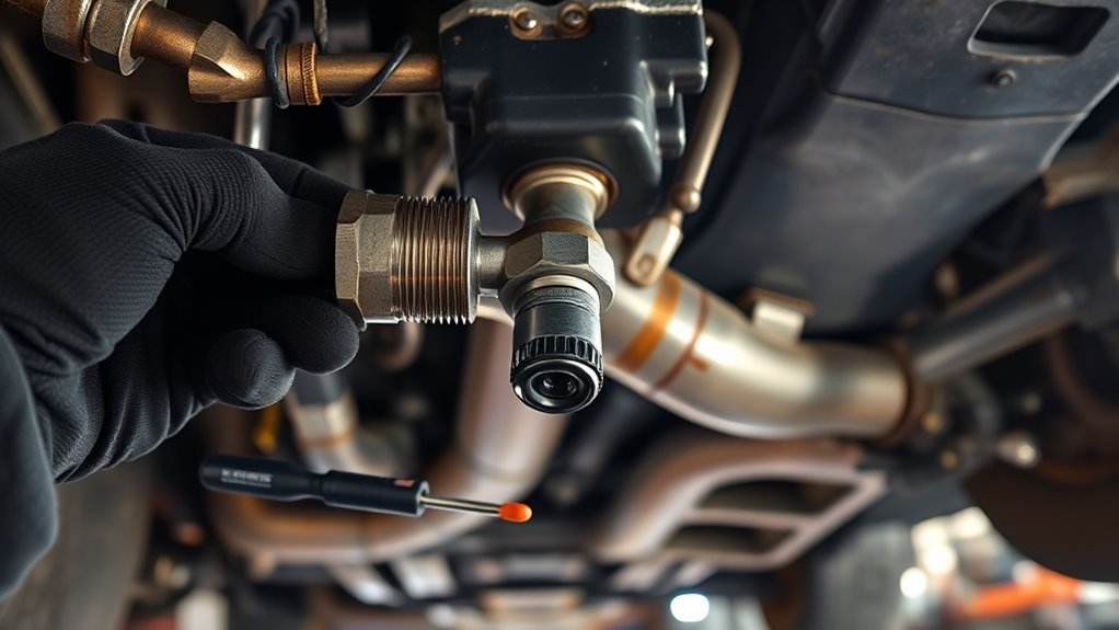
Apply a small amount of penetrating oil only to the exposed threads or flange fasteners. Keep it away from the electrical connector and sensor tip, then allow time for it to work.
Choose the removal path that matches the mounting style:
- For a threaded sensor: confirm that the lead is unplugged and free from its clips. Place the slotted socket or approved wrench fully onto the hex and apply smooth, controlled force. If the sensor binds after it starts moving, work it gently back and forth instead of forcing it through damaged threads.
- For a flange-mounted sensor: support the sensor plate and loosen the two fasteners gradually. Alternate between the fasteners when corrosion allows, then remove the plate and old gasket without gouging the sealing surface.
- Inspect the mounting point: check the bung threads, flange face, studs, nuts, and bolts for rust, distortion, erosion, or cross-thread damage.
- Clean carefully: remove loose soot and old gasket material without pushing debris into the exhaust opening.
If a stud turns, a nut rounds, or the bung threads are damaged, stop and repair the mounting point before installing the new sensor. A forced installation can create an exhaust leak, ruin the new sensor’s threads, and damage the replacement.
Pro tip: Take a clear photo of the sensor, connector, clips, heat shields, and complete harness route before removing any retainers.
[Products Worth Considering]

This oxygen O2 sensor set is designed for select Toyota Camry and RAV4 models with 2.4L engines, providing upstream and downstream replacement coverage in one package. Built to OEM specifications for plug-and-play installation, it helps improve fuel efficiency, support accurate air-fuel monitoring, and restore reliable engine performance. The stainless steel and heat-resistant construction is made for long-lasting durability and stable operation.

This odor control cabin air filter uses activated charcoal and baking soda to help neutralize unwanted smells while trapping dust, pollen, soot, dander, and other airborne contaminants. Designed for compatible Toyota, Lexus, Subaru, and select other vehicles, it supports cleaner cabin air and balanced HVAC airflow for everyday driving comfort. Installation is straightforward, with vehicle-specific guidance available to help make replacement quick and easy.

EPAuto CP134 is a premium cabin air filter designed to help keep the air inside your vehicle cleaner and fresher. It includes activated carbon to help reduce odors and support a more comfortable ride for drivers and passengers. Built as a replacement option for many Honda and Acura models, it offers broad compatibility and dependable cabin air filtration.
How Do You Install a Threaded or Flange-Mounted Upstream Sensor?
Compare the replacement with the removed part again. The connector, terminal layout, wire length, mounting design, protective sleeve, and sensor body must match. Do not splice a universal sensor into the factory harness unless the sensor manufacturer and vehicle service information specifically support that method.
Keep grease, penetrating oil, gasket debris, excess anti-seize, and sealant off the sensing tip, vents, harness, and connector. Handle the replacement by its body and protected harness.
[Products Worth Considering]

This scissor car jack kit provides a dependable solution for emergency tire changes and roadside repairs. With a lifting range suited for low sedans and higher-body SUVs, it comes with essential tools like a ratchet wrench, lug wrench, gloves, tire pressure gauge, and storage bag for convenient use and transport. Built for stability and ease of operation, it is a practical all-in-one kit for cars, SUVs, and MPVs.
This EL-50448 TPMS relearn tool helps quickly activate and reset tire pressure sensors so your vehicle’s monitoring system stays accurate after tire rotations, sensor replacement, or seasonal tire changes. Designed for many GM-related vehicles and compatible with common 315 and 433 MHz TPMS systems, it offers simple one-button operation and reliable performance for clearing warning lights and relearning sensor positions.

[Vehicle Fitment]: Compatible with Lexus LX470 1998-2005 V8 4.7L; Compatible with Toyota 4Runner 1996-2000 L4 2.7L, 4Runner 1996-2000 V6 3.4L, Land Cruiser 1998-2005 V8 4.7L, Pickup 1994-1995 V6 3.0L, Sequoia 2001-2004 V8 4.7L, T100 1995-1998 L4 2.7L, T100 1995-1998 V6 3.4L, Tacoma 1995-1999 L4 2.4L, Tacoma 1995-1997 L4 2.7L, Tacoma 1995-2000 V6 3.4L, Tundra 2000-2004 V6 3.4L, Tundra 2000-2004 V8 4.7L, Tacoma 1999-2000 L4 2.7L
How Do You Install a Flange-Mounted Sensor and Gasket?
Clean the flange face, place the specified new gasket in the correct orientation, and align the sensor plate without twisting the harness. Start both fasteners by hand so the plate remains square to the flange.
- Confirm that the gasket holes and exhaust opening align.
- Start both nuts or bolts by hand.
- Tighten the fasteners in small, alternating steps.
- Finish at the exact torque listed for the model, sensor plate, and fastener.
Do not reuse a crushed, split, corroded, or heat-damaged gasket. If the plate will not sit flat, remove it and find the obstruction instead of using extra torque.
How Do You Install a Threaded Sensor?
Check whether the new sensor arrives with thread compound already applied. Do not add more unless the sensor manufacturer instructs you to do so. DENSO advises applying only a moderate amount when lubricant is not pre-applied and keeping the sensor nose clean.
Guide the sensor into the bung while keeping the wire relaxed. Turn it by hand for several full threads. If it does not turn smoothly, back it out and inspect the threads before using a wrench.
Once hand-started, tighten the sensor with the correct tool to the exact specification for the truck and replacement part. Do not allow the harness to wind around the sensor body while tightening.
How Do You Verify Torque and Seating?
- Use the exact specification: check Toyota service information for the model year and engine or the instructions supplied with the direct-fit sensor.
- Account for the tool: a crowfoot or special service tool can change effective torque when its position changes the torque wrench’s working length.
- Check the seal: confirm that a threaded sensor is fully seated or a flange plate sits flat with an even gasket line.
- Check the harness: make sure tightening did not wind, stretch, rub, or pinch the lead.
Verified example, not a universal Tacoma specification: Service information for a 2005 Tacoma 2WD 2.7L 2TR-FE specifies 44 N·m (33 ft-lb), or 40 N·m (30 ft-lb) when the listed special service tool is used with the specified torque-wrench geometry. Do not apply these values to a flange-mounted sensor, a 2024+ truck, or another application without confirmation.
The generic 30-to-40 ft-lb range repeated in online discussions is not reliable for every Tacoma sensor design. Thread size, sensor construction, flange hardware, gasket design, tool geometry, and model-specific instructions can change the required torque.
How Do You Route and Reconnect the Sensor Wiring?
Route the new O2 sensor harness along the photographed factory path and secure it in the original retainers. The lead must stay clear of the exhaust, steering parts, belts, driveshaft, suspension movement, hoses, and sharp edges.
Use the original clips when they still lock firmly. Replace a broken clip with the correct retainer rather than pulling the harness tight with a general-purpose tie placed near the exhaust.
Inspect the connector pins, align the housings, and push them together until the lock clicks. Gently pull on the housings, not the wires, to confirm the connection is secure.
Finish with a full visual check. The harness should have enough slack for engine movement but no loose loop that can contact a hot or moving part.
How Do You Test the Repair and Troubleshoot a Returning Check Engine Light?
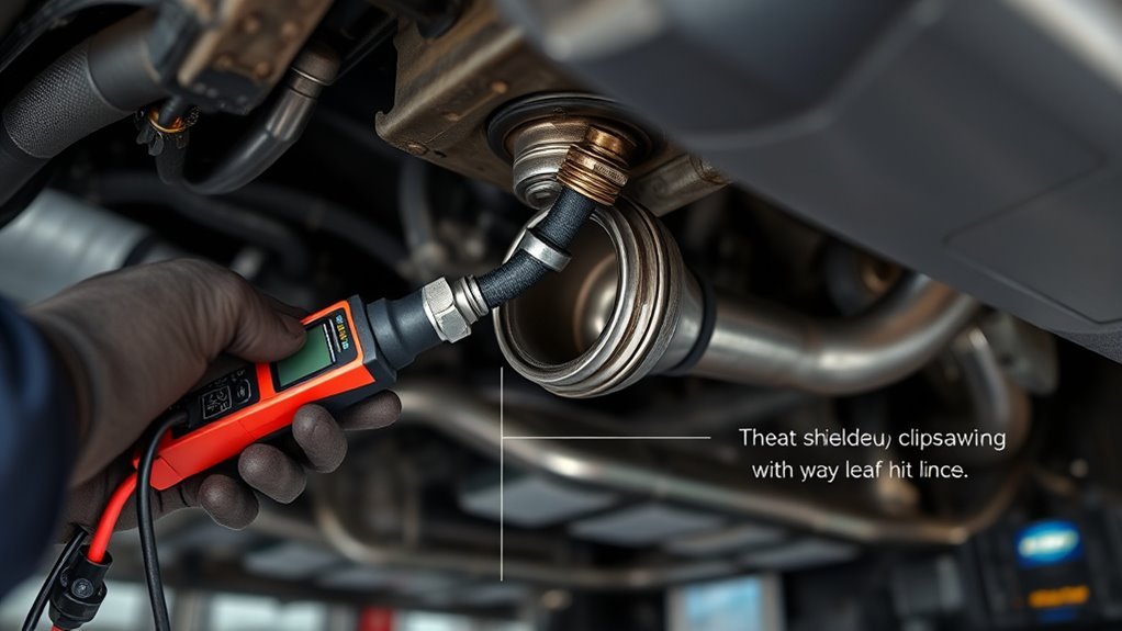
Before starting the engine, recheck the fasteners, connector lock, harness clearance, tools, and any battery connection you removed. Confirm the sensor is seated and that a flange gasket is not pinched or protruding abnormally from the joint.
Use the exact torque for the installed design, restore the factory wire route, then verify the exhaust seal, code status, live data, and readiness monitors.
- Reconnect the negative battery terminal only if you disconnected it, using the vehicle’s specified terminal procedure.
- Start the engine and listen near the repaired joint for a sharp ticking, puffing, or hissing sound.
- Look for fresh soot or evidence of leakage around the bung or flange after the engine has run.
- Scan for current, pending, and permanent diagnostic trouble codes.
- Review the correct A/F-sensor or O2-sensor data for the model rather than assuming every front sensor should switch like a narrowband sensor.
- Clear codes only after saving the original information and completing the repair.
- Recheck the connector, heater circuit, relay, exhaust seal, intake system, and fuel-trim data if the light or pending code returns.
A permanent DTC may remain visible until the ECM reruns the applicable monitor and confirms that the fault is no longer present. Clearing codes or disconnecting the battery can also reset emissions-readiness monitors. The truck may need normal drive cycles before all supported monitors show complete.
Check the scanner’s I/M readiness screen before an emissions inspection. For the next steps, see the Tacoma OBD2 readiness-monitor guide. The U.S. EPA also explains that a recent OBD reset or battery disconnection can leave monitors in a not-ready state in its vehicle inspection and OBD-readiness guidance.
If the same code returns, do not replace another sensor without diagnosis. The cause may be connector damage, a heater power or ground fault, a failed relay, an intake or exhaust leak, a fuel-control problem, a wiring fault, or a catalytic-converter issue.
Note: Toyota may call the upstream unit an air-fuel ratio sensor rather than a conventional oxygen sensor. Match the replacement by VIN, engine, emissions package, connector, wire length, and mounting design.
[Products Worth Considering]

【Diagnose Check Engine Light in Seconds – No Mechanic Needed】The FOXWELL NT301 OBD2 scanner instantly reads & clears engine fault codes (DTCs) with one click. Simply plug into the 16-pin DLC port, turn ignition on, and get accurate results within seconds—No prior car knowledge required. Save hundreds on dealership fees by knowing exactly what’s wrong before you visit a shop. The #1 choice car scanner for DIYers and car owners who want to take control of their vehicle’s health

APPLICABLE MODELS - Air Fuel Ratio Sensor Compatible with Tacoma 2.4L L4 1995-2000 Tacoma 2.7L L4 1996-2000 Tacoma 3.4L V6 1999-2000 Tundra 4.7L V8 2000-2002.

【Compatible Vehicle Model】Oxygen sensor Compatible with Toyota: 4Runner 1996-2000(2.7L/L4&3.4L/V6); T100 1995-1998(2.7L/L4&3.4L/V6); Tacoma 1995-2000(2.4L 2.7L/L4&3.4L/V6); Tundra 2000-2004(4.7L/V8); Sequoia 2001-2004(4.7L/V8); Pickup 1994-1995(3.0L/V6)
Frequently Asked Questions
Can I Replace My Tacoma’s Upstream O2 Sensor Myself?
Yes, if you have safe access, the correct direct-fit part, the proper tool for the visible mounting style, and the exact torque specification. Stop if the exhaust hardware, bung threads, flange studs, connector, or harness is damaged.
Which Sensor Is Bank 1 Sensor 1 on a 4-Cylinder Tacoma?
Bank 1 Sensor 1 is the upstream or pre-catalyst sensor used for fuel-control feedback. An inline four-cylinder engine has one cylinder bank, but the sensor’s exact position, name, connector, and access route still depend on the model year, engine, emissions calibration, and exhaust layout.
Is the Upstream Tacoma Sensor an O2 Sensor or an Air-Fuel Ratio Sensor?
It depends on the model year and calibration. Parts stores and generic scan-code descriptions may call it an oxygen sensor, while Toyota service information for many applications calls Bank 1 Sensor 1 an air-fuel ratio or A/F sensor. Use the VIN, emissions label, catalog description, connector, and service information to identify the correct part and data interpretation.
What Codes Can Point to Tacoma Bank 1 Sensor 1?
Depending on the model year, examples include P0031/P0032 for the upstream A/F heater circuit, P2195/P2196 for a signal biased or stuck lean or rich, and P2237–P2239 or P2252–P2253 for pumping-current circuit faults. P0171, P0172, or P0420 may involve sensor data but do not prove that Bank 1 Sensor 1 itself has failed.
How Much Does It Cost to Replace the Oxygen Sensor on a Toyota Tacoma?
The total varies with the model year, direct-fit sensor, local labor rate, access, and exhaust corrosion. Third-party repair-estimate aggregators put a typical Tacoma oxygen/A-F sensor replacement in a roughly $200–$500 range depending on the source and sensor position, but these are general estimates, not a quote for a specific VIN — see RepairPal’s Tacoma oxygen sensor cost estimator for a sample range, then compare it against a written quote for the exact part and labor on your truck. Seized flange hardware, a damaged connector, broken studs, or damaged bung threads can add substantial labor.
Can I Drive My Truck With a Bad Upstream Sensor?
A short trip to a safe location or repair appointment may be possible when the truck runs normally and the check engine light is steady, but avoid unnecessary driving until you diagnose the fault. Stop driving if the light flashes, the engine misfires or shakes, power drops sharply, the engine overheats, or you smell raw fuel.
Do I Need to Clear the Check Engine Light After Replacing the Sensor?
Not always. Record the codes and freeze-frame data first. After the repair, you can clear the codes with a scan tool or allow the system to rerun its monitors. Clearing codes or disconnecting the battery also resets readiness information, and a permanent code may remain until the applicable monitor confirms the repair.
Should I Use Anti-Seize on a New O2 Sensor?
Use anti-seize only when the replacement sensor does not already have thread compound and its manufacturer permits application. Apply only the specified amount to the threads, and keep it off the sensing tip, vents, harness, and connector. A flange-mounted sensor normally uses its specified gasket rather than thread compound on the sensor body.
Conclusion
A successful upstream O2 sensor replacement starts with application identification, not removal. Confirm the Tacoma’s model year, engine, emissions certification, Bank 1 Sensor 1 designation, connector, and mounting style. Do not apply an older 2TR-FE or flange-mounted procedure to a 2024–2026 turbo or hybrid truck without VIN-specific service information.
Diagnose the code family, inspect the heater circuit and exhaust, install the exact part with the correct seal and torque, and restore every harness clip. After startup, check for leaks, rescan the truck, and verify readiness before an emissions inspection. If the same code returns, diagnose the wiring, leaks, fuel control, and catalyst system instead of replacing another sensor by guesswork.