
Last updated: September 16, 2026. [VERIFY: add real author/byline and automotive credentials]
On many Toyota Camrys, the sensor before the catalytic converter is an air-fuel ratio (A/F) sensor used for precise fuel control, while a sensor after the converter may be a conventional oxygen sensor used mainly for catalyst monitoring. That layout is not universal across every Camry generation, engine, hybrid system, or emissions calibration. Some later Toyota service information identifies downstream Sensor 2 as an A/F (O2) sensor too. Mixing up the sensor type can lead to the wrong part, the wrong electrical test, and a Check Engine light that keeps coming back.
Quick Answer
A Camry’s Sensor 1 is upstream of the catalytic converter and provides mixture feedback to the ECU. On many generations it is a wide-range A/F sensor. Sensor 2 is downstream, but do not assume it is always a conventional narrowband O2 sensor because Toyota uses different sensor strategies across model years and powertrains. Confirm the VIN, VECI label, engine, bank/sensor position, connector, and Toyota service data before ordering or testing either sensor.
Key Takeaways
- Sensor 1 is upstream of the catalytic converter; Sensor 2 is downstream. The position number does not always prove which sensor technology Toyota used.
- A/F sensors are wide-range sensors used for precise mixture feedback; conventional narrowband O2 sensors switch rich/lean near stoichiometric.
- Do not test a Toyota A/F sensor as if it were a simple 0.1–0.9 V narrowband O2 sensor.
- A generic scanner may use the words “oxygen sensor” in a DTC title even when Toyota service information identifies the affected component as an A/F sensor.
- Codes point toward a circuit or operating condition. Wiring, exhaust leaks, coolant temperature, fuel trims, intake leaks, and fuel-delivery faults must be checked before replacing a sensor.
- Always confirm the exact part by VIN, emissions label, engine, connector, bank/sensor position, and service manual.
At a Glance
| Time Required | No single Camry-wide time applies. Diagnostic time and physical access vary by engine, exhaust layout, corrosion, and sensor position. |
| Difficulty | Beginner to intermediate for identification and scan checks; intermediate for replacement because exhaust heat, seized threads, and tight access are common. |
| Tools Needed | OBD-II scanner with appropriate live-data capability, Toyota service information or repair manual, oxygen-sensor socket if replacement is required, DVOM when the factory test procedure calls for one, penetrating oil, torque wrench, gloves, eye protection, and properly rated jack stands if the vehicle must be raised. |
| Cost | Varies by model year, engine, emissions specification, sensor technology, and sensor position. Verify the VIN-based part before buying. |
Who This Guide Is For and How to Use It
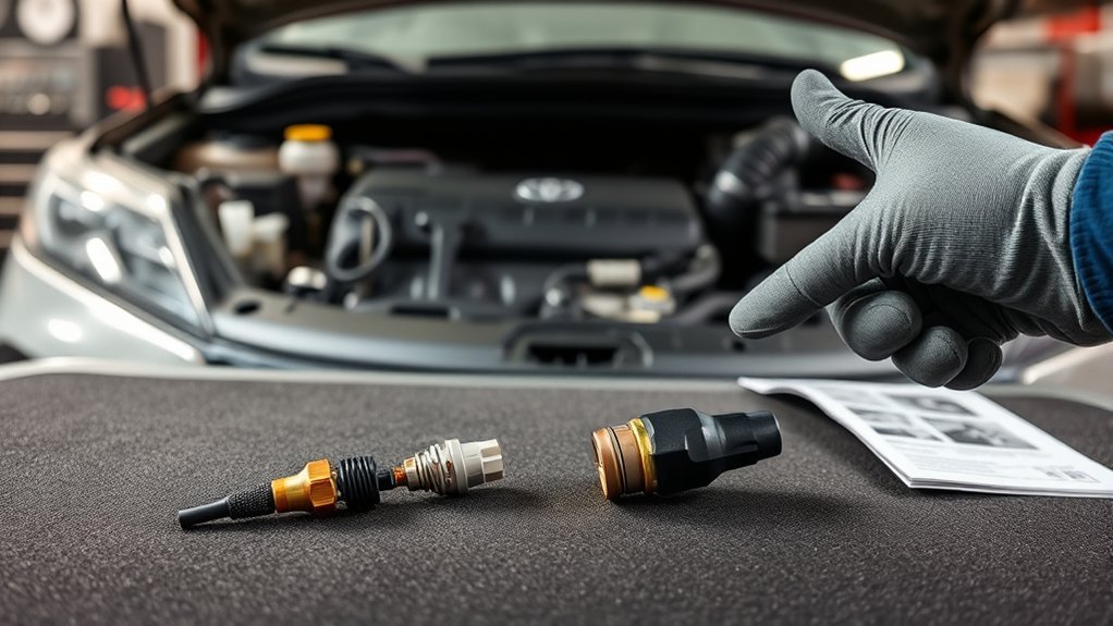
This guide is for Camry owners, DIYers, and technicians who need to identify an oxygen sensor or air-fuel ratio sensor before diagnosing a code or ordering a part. The examples cover multiple gasoline and hybrid-era Toyota strategies, but the exact sensor type, count, location, signal, and diagnostic procedure can change by model year, engine, market, emissions certification, and powertrain.
Use this guide in order: identify the sensor position, confirm the VIN and emissions label, read all codes and freeze-frame data, check Toyota-specific live data, and inspect wiring and related engine problems. Do not start by replacing a sensor simply because a generic code description includes O2, oxygen sensor, A/F, or heater circuit.
Note: Toyota’s Technical Information System is the factory service source for repair manuals, wiring diagrams, technical training, and diagnostic information. A scan tool and a generic parts listing are useful, but model-specific service data should win when there is a conflict.
Important: Do not use “Sensor 1 = A/F sensor” and “Sensor 2 = conventional O2 sensor” as a universal Camry parts rule. Sensor 1 and Sensor 2 identify position relative to the catalytic converter; the sensing technology must still be confirmed for the exact vehicle.
Quick Symptoms: Camry O2 & A/F Sensor Problems to Watch For
Sensor or sensor-circuit problems usually start with a Check Engine light, stored diagnostic trouble code, failed readiness monitor, or abnormal live data. Depending on the position and Toyota calibration, you may also notice poor fuel economy, rough idle, hesitation, failed emissions inspection, or catalyst-related codes. These symptoms are not proof that the sensor itself has failed.
Check Engine Light
If the Check Engine light comes on, read all current, pending, and history codes plus freeze-frame data before clearing anything. A code identifies the circuit, monitor, or condition that failed; it does not automatically prove that the named sensor needs replacement.
| Code Example | What It Can Mean | First Checks |
|---|---|---|
| P1130 | Older Toyota-specific A/F Sensor Circuit Range/Performance example for Bank 1 Sensor 1. It is documented on early-2000s Camry applications but is not a universal Camry code. | A/F live data, short-term fuel trim, intake leaks, exhaust leaks, fuel pressure, injector operation, wiring |
| P1155 | Older Toyota-specific A/F sensor heater-circuit example for Bank 2 Sensor 1 on applicable V6 models. | Heater power/current, relay or supply circuit, connector fit, corrosion, open or short in wiring |
| P2195 / P2196 | Later Toyota applications may describe these as oxygen-sensor stuck-lean/stuck-rich codes even though Toyota service information states that they relate to the upstream A/F sensor. | A/F current or calculated voltage, fuel trims, intake/exhaust leaks, fuel delivery, wiring, active-test response |
| P2A00 | A/F sensor circuit slow-response example used on applicable Camry engines. | Sensor response, wiring, exhaust leaks, intake leaks, fuel delivery, contamination, Toyota confirmation procedure |
These are examples spanning different Toyota generations, not a universal code list. Code wording and diagnostic logic change by year, engine, emissions package, and scan-tool database. Always compare the scanner description with Toyota repair information for the exact VIN.
Reduced Fuel Economy
An upstream A/F-sensor problem can make fuel-control feedback inaccurate, which may show up as lower MPG, unusual fuel trims, hesitation, or a fuel smell. However, some later Toyota strategies also use downstream A/F-sensor information differently from older narrowband layouts. Diagnose the exact sensor and calibration rather than assuming every downstream fault affects only catalyst monitoring. For related maintenance context, see the Camry oxygen-sensor lifespan guide.
Rough Idle or Stalling
Rough idle, hesitation, and stalling can occur when mixture feedback is wrong, but these symptoms are not sensor-specific. Vacuum leaks, incorrect MAF data, fuel-pressure problems, injector faults, misfires, coolant-temperature faults, PCV faults, and exhaust leaks can imitate a bad O2 or A/F sensor.
Warning: Do not replace a sensor just because the code mentions that sensor. A wiring fault, air leak, exhaust leak, fuel-system problem, or another engine fault can set the same code and make a new sensor appear “bad.”
Identify Your Camry’s Sensor: VECI, VIN, and Connector Colors
Start with three checks: the underhood emissions label, the VIN-based parts catalog, and the connector/wiring shown in the repair manual. Toyota used different sensor layouts across Camry generations, engines, hybrid and non-hybrid models, emissions calibrations, and markets.
Check the VECI Label
The Vehicle Emission Control Information label is located under the hood or in the engine compartment on U.S.-market light-duty vehicles. EPA identifies it as the “Vehicle Emission Control Information” label. Use the test-group or emissions-family information together with the VIN and Toyota service data when identifying emissions components; do not use the label alone as a substitute for a parts catalog or wiring diagram.
Confirm by VIN
A sensor that physically threads into one Camry exhaust may still be electrically wrong for another Camry with the same body style. Before buying, match the VIN, production information when applicable, engine, emissions specification, bank/sensor position, connector shape, wire length, and Toyota or direct-fit catalog application. Do not rely on a part-number prefix or physical appearance alone.
Inspect Connector Wire Colors
Look at the sensor connector, pin count, wire routing, and harness condition. Photograph the connector before unplugging it. Then compare it with the wiring diagram. Do not rely on wire color alone because harness colors, terminals, and connector layouts can change by year, engine, and sensor technology.
Pro Tip: A parts catalog or scanner may use “oxygen sensor” as a broad label even when Toyota service information calls the component an air-fuel ratio sensor. Identify the part by the vehicle and Toyota’s service description, not the generic category name alone.
What Do Sensor 1 and Sensor 2 Do on a Toyota Camry?
Sensor 1 is upstream of the catalytic converter. Its feedback is used to evaluate and control the air-fuel mixture. On many Camrys, this unit is a wide-range A/F sensor rather than a conventional narrowband O2 sensor.
Sensor 2 is downstream of the relevant catalytic converter. On many older or conventional layouts it is a narrowband heated oxygen sensor used heavily for catalyst monitoring. However, Toyota service information for some later Camry powertrains identifies Sensor 2 as an air-fuel-ratio sensor. That is why “Sensor 2” tells you location but does not always tell you sensor technology.
- Bank 1 Sensor 1: upstream sensor on the bank containing cylinder No. 1.
- Bank 2 Sensor 1: upstream sensor on the other bank of a V-type engine.
- Bank 1 Sensor 2: downstream/post-catalyst sensor on Bank 1; confirm whether Toyota specifies a conventional O2 or A/F sensor for the exact application.
- Bank 2 Sensor 2: downstream/post-catalyst sensor on Bank 2 where equipped; again, confirm sensor technology from service data.
Inline 4-cylinder Camrys normally have only Bank 1. V6 Camrys have Bank 1 and Bank 2, so bank identification matters before you buy a sensor, unplug a connector, or test the wrong circuit.
Signal Differences: Narrowband O2 vs. Wideband/A-F Sensor
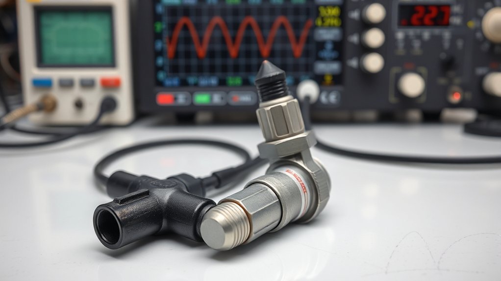
A warmed-up conventional narrowband O2 sensor behaves mainly like a rich/lean switch near stoichiometric mixture. Many narrowband applications move roughly from about 0.1 V on the lean side toward about 0.9 V on the rich side during closed-loop operation.
A Toyota A/F sensor is different. It is a wide-range sensor that lets the ECU evaluate mixture more precisely. Do not expect its circuit to behave like a simple 0.1–0.9 V narrowband signal. Toyota scan data may display an ECM-calculated A/F voltage, sensor current, lambda value, or a combination of parameters depending on the generation. Older Toyota documentation commonly shows an A/F scan value centered near about 3.3 V, while later Camry data can use different normal ranges and current-based parameters.
For example, some later Toyota service data lists A/F-sensor voltage in roughly the 2.6–3.8 V range at warm idle and sensor current near zero around stoichiometric operation. Those values are application-specific examples, not universal specifications. Use the exact Toyota data-list range and active-test procedure for your VIN.
DENSO describes A/F sensors as wide-band oxygen sensors with a broader response range for finer mixture control. That broader range is why sensor identification and the correct scan-data parameter matter before diagnosis.
Note: Do not pierce sensor wires or assume that a scan-tool voltage is the same voltage you can measure directly at the sensor terminals. Toyota documentation for A/F systems can specify that the displayed voltage is calculated inside the ECM. Back-probing incorrectly can damage wiring, spread terminals, or create a new intermittent fault.
[Products Worth Considering]

The FOXWELL NT301 is a plug-and-play OBD2 code reader designed to help drivers and home mechanics diagnose check engine light issues with ease. It reads fault codes, clears emissions-related warnings, displays live sensor data in graph form, and shows I/M readiness so you can quickly check vehicle status before an emissions test. With broad compatibility across many OBD2 vehicles and a clear color screen, it offers a practical, user-friendly way to monitor and troubleshoot engine performance.

This oxygen O2 sensor set is designed for select Toyota Camry and RAV4 models with 2.4L engines, providing upstream and downstream replacement coverage in one package. Built to OEM specifications for plug-and-play installation, it helps improve fuel efficiency, support accurate air-fuel monitoring, and restore reliable engine performance. The stainless steel and heat-resistant construction is made for long-lasting durability and stable operation.

This mass air flow sensor is designed to replace compatible OEM parts for a wide range of Toyota and Lexus vehicles, helping restore accurate airflow readings and smoother engine operation. It is computer-tested for stable signal output, fast response, and improved fuel efficiency, while also supporting reliable performance under demanding driving conditions. The easy-install design makes replacement straightforward, and a 12-month warranty adds extra peace of mind.
How Do You Diagnose a Camry O2 or A/F Sensor Code?
Diagnose the code in layers. Start with stored evidence, confirm which sensor technology Toyota uses at that position, inspect the circuit, and then evaluate live data and engine conditions. Replacing the sensor should come after the basic checks, not before them.
- Record all codes and freeze-frame data. Note engine temperature, speed, load, fuel trims, and whether the code set during warm-up, cruise, idle, acceleration, or fuel cut.
- Confirm the Toyota definition. A generic scanner may label a code as an “O2 sensor” fault even when Toyota describes that position as an A/F sensor.
- Check for related codes. Misfire, MAF, coolant-temperature, fuel-trim, heater, or catalyst codes can change the diagnosis.
- Inspect the harness. Look for melted insulation, oil contamination, corrosion, loose terminals, stretched wires, damaged loom, and previous repairs.
- Check for exhaust leaks. A leak ahead of a sensor can introduce outside oxygen and distort mixture-related data.
- Check intake and fuel issues. Vacuum leaks, incorrect MAF readings, fuel-pressure faults, injector problems, purge faults, and PCV leaks can all make a good sensor report abnormal mixture.
- Test the heater circuit using the factory procedure. Verify the specified power supply, ground/control, resistance, current, or duty data. Do not transfer a narrowband O2-sensor test method to an A/F sensor without confirming the circuit design.
- Use active tests if available. With Toyota Techstream or a capable scan tool, command the Toyota-specified mixture change and watch the applicable A/F and downstream sensor parameters.
- Repair the root cause, then verify. Clear codes only after documenting the original data and completing the repair. Recheck live data and readiness status afterward.
[Products Worth Considering]
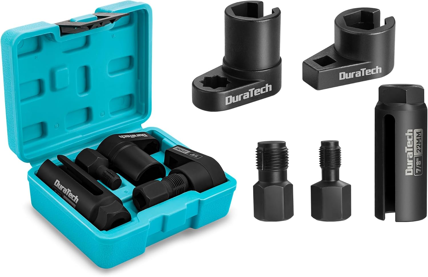
This DURATECH O2 sensor socket set is designed to help remove, inspect, replace, and install oxygen sensors and vacuum switches on many computer-controlled vehicles. It includes offset and long sockets plus two thread chasers for cleaning and repairing damaged threads, making sensor service easier and more reliable. Built from alloy steel with a secure slotted design, it offers practical performance and durability for automotive repair work.

The BLCKTEC 440 Bluetooth OBD2 scanner helps drivers and DIY mechanics quickly read and clear trouble codes, monitor live data, and check emissions readiness with confidence. Its color display, graphing capabilities, and battery and charging system testing make it a versatile diagnostic tool for OBD-compliant vehicles. Designed for plug-and-play convenience, it runs directly from your vehicle and includes support for report sharing and ongoing updates.

This plug-and-play OBD2 scanner helps drivers quickly read and clear engine error codes while providing live data, freeze frame information, I/M readiness, and MIL status for more confident troubleshooting. It adds a built-in voltage test and clear status indicators to support electrical checks and faster diagnostics, making it a practical choice for home users, car enthusiasts, and repair professionals. Compatible with most OBDII vehicles since 1996 and designed with an easy-to-use interface, it offers broad coverage and simple operation in one compact tool.
Replacing Sensors: Correct Parts, Heater Tests, Torque, and Sealant
Before removing a sensor, confirm the part by VIN, engine, sensor technology, bank/sensor position, connector, wire length, and emissions specification. A sensor can fit the exhaust threads and still be electrically or calibration-wise wrong for the ECU.
Warning: Exhaust parts can stay hot long after shutdown. Let the exhaust cool, wear eye protection, and use properly rated jack stands at the correct lift/support points if the vehicle must be raised. Never work under a vehicle supported only by a jack.
Use this replacement checklist:
- Disconnect the connector without twisting the harness. Release the retaining clips carefully.
- Apply penetrating oil if removal is difficult. Keep chemicals away from the connector and sensing element.
- Use the correct oxygen-sensor socket or Toyota-specified SST. Do not use an impact wrench to install the new sensor.
- Compare the parts before installation. Match thread size, tip design, connector, wire length, shielding, and catalog application.
- Apply anti-seize only when the sensor manufacturer’s instructions call for it. Many replacement sensors are already treated. Keep compound away from the sensing element.
- Start the sensor by hand. Cross-threading an exhaust bung or manifold can turn a sensor replacement into a larger exhaust repair.
- Torque to the exact specification. NGK’s general M18 installation guidance is 26–33 ft-lb, but Toyota’s service-manual specification and the replacement-sensor manufacturer’s instructions override a generic range.
- Route the wire exactly like the original. Keep it away from hot exhaust parts, axle shafts, fans, belts, and sharp brackets.
- Perform any Toyota-required inspection after repair. Recheck for exhaust leaks, confirm live data, clear codes only when appropriate, and verify that monitors complete without the fault returning.
Pro Tip: If the old sensor is heavily sooted, oily, coolant-contaminated, or coated with unusual deposits, treat that as diagnostic evidence. Look for rich operation, oil consumption, coolant intrusion, silicone contamination, or another upstream engine problem before installing a new sensor.
[Products Worth Considering]

FOXWELL NT201 is an easy-to-use OBD2 scanner designed to help drivers quickly read and clear check engine codes, view live engine data, and check emissions readiness. Its color screen, one-key I/M readiness test, and broad compatibility with most gasoline vehicles since 1996 make it a practical tool for everyday diagnostics and maintenance. With plug-and-play operation and lifetime free updates, it offers a simple way to understand vehicle issues without expensive shop visits.

The ANCEL AD310 is a compact, easy-to-use OBD II code reader designed to help drivers quickly identify check engine light causes, read and clear fault codes, and review key vehicle data. It supports major OBD2 protocols and works with many 1996-and-newer cars, light trucks, SUVs, and other OBD2 vehicles. Built for fast diagnostics at home or on the go, it runs directly from the vehicle and provides clear results on a large screen.

Walker exhaust pipe flange gasket is designed to help complete exhaust repairs with a reliable seal for compatible vehicles. Built to work with OE exhaust components and Walker replacement parts, it features heat-deflecting construction, durable materials, and slotted bolt holes where applicable for easier installation. Engineered and tested for real-world performance, it supports long-lasting exhaust system service.
Emissions Impact, Fuel Economy, and When to Call a Pro
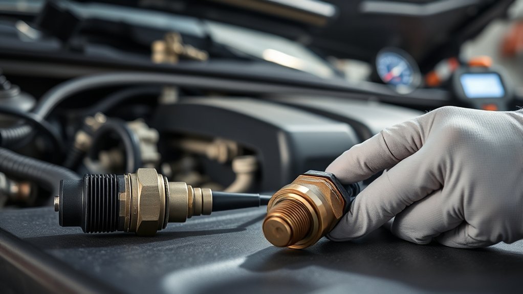
A faulty mixture-feedback sensor or circuit can distort fuel-control information, increase emissions, reduce economy, affect readiness monitoring, and in some cases contribute to conditions that stress the catalytic converter. A downstream-sensor fault can also interfere with catalyst monitoring even when the vehicle appears to drive normally. The exact control strategy depends on the Camry’s year and powertrain.
Repair the sensor circuit and the condition that caused the fault; do not bypass emissions monitoring. OBD is designed to detect emissions-related malfunctions, alert the driver, and store diagnostic information that helps identify the fault.
Call a professional if the sensor is seized, access requires major component removal, the code returns after a verified correct-part replacement, fuel trims remain far from the Toyota-specified range, electrical tests require circuit knowledge you do not have, or multiple emissions codes appear together. A shop with Toyota Techstream or an equivalent scan tool can run active tests, compare data against factory specifications, and determine whether the sensor, wiring, ECU input, exhaust system, or engine condition is the real cause.
Frequently Asked Questions
What is the difference between an oxygen sensor and an air-fuel ratio sensor?
A conventional narrowband oxygen sensor primarily switches rich or lean near stoichiometric mixture. An air-fuel ratio sensor is a wide-range oxygen-sensing device that gives the ECU more precise mixture information. Toyota may use different sensor types at different exhaust positions depending on the Camry generation and powertrain.
Do O2 sensors read AFR?
A conventional narrowband O2 sensor does not provide a precise air-fuel-ratio value across a wide range. It mainly indicates rich or lean around stoichiometric. A wide-range A/F sensor gives the ECU substantially more precise mixture feedback.
What is an AFR O2 sensor?
“AFR O2 sensor” is a common catalog or scan-tool phrase for an air-fuel ratio sensor. It still detects oxygen in the exhaust, but its operating strategy and diagnostic data differ from a conventional narrowband O2 sensor.
Can I replace a Camry A/F sensor with a regular O2 sensor?
No, not unless Toyota’s application data specifically identifies the replacement as correct. Similar threads do not make the sensors interchangeable. Signal strategy, heater control, connector, calibration, and ECU interpretation can differ. Use the exact sensor specified for the VIN, engine, bank, and position.
Is Bank 1 Sensor 1 the upstream sensor?
Yes. Sensor 1 is upstream of the relevant catalytic converter. Bank 1 is the engine bank containing cylinder No. 1. An inline 4-cylinder Camry normally has only Bank 1, while a V6 has Bank 1 and Bank 2.
Is Sensor 2 always a conventional oxygen sensor on a Camry?
No. Sensor 2 always identifies a downstream position, but the sensor technology varies. Many Camrys use a conventional heated O2 sensor downstream, while Toyota service information for some later Camry powertrains identifies Sensor 2 as an A/F sensor. Confirm the exact application before testing or ordering.
Why does my scanner say “oxygen sensor” when Toyota calls it an A/F sensor?
Generic OBD terminology can use “oxygen sensor” in a DTC title even when Toyota’s repair information identifies the component as an air-fuel ratio sensor. P2195 and P2196 are examples on applicable Toyota engines. Use Toyota service data to determine the actual component and test procedure.
Should I replace both sensors at the same time?
Not automatically. Replace a sensor only after diagnosis confirms that sensor or its circuit has failed. Replacing extra sensors can waste money and will not repair an intake leak, exhaust leak, wiring fault, fuel-delivery problem, or other engine condition.
Why did the Check Engine light return after replacing the sensor?
The replacement may be wrong for the VIN or sensor position, the connector may be loose, the heater or signal circuit may have a wiring fault, or the engine may still have an intake, fuel, exhaust, temperature, or misfire problem that caused the original code. Compare the returning code and freeze-frame data with the pre-repair evidence instead of replacing another part immediately.
Conclusion
The safest way to distinguish a Toyota Camry O2 sensor from an air-fuel ratio sensor is to identify the vehicle and sensor position before interpreting the signal. Sensor 1 is upstream and provides mixture feedback, but Sensor 2 is not automatically a conventional narrowband O2 sensor on every Camry. Confirm the VIN, engine, VECI information, bank/sensor position, connector, and Toyota service description first. Then diagnose codes, wiring, heater operation, live data, fuel trims, intake leaks, exhaust leaks, and fuel-delivery problems before replacing anything.
Sources
- Toyota Technical Information System — Toyota service information, repair manuals, wiring diagrams, technical training, and diagnostic procedures.
- DENSO A/F Sensors — wide-band air-fuel sensor operation, positioning, and mixture-control role.
- DENSO O2 and A/F Sensor Troubleshooting — diagnostic workflow and sensor troubleshooting guidance.
- NGK Oxygen Sensor Installation — anti-seize, routing, handling, and general M18/M12 torque guidance.
- U.S. EPA: Locating the Vehicle Emissions Label — VECI/emissions-label identification and location.
- California Air Resources Board: OBD Program — onboard emissions monitoring and diagnostic-system context.