If your Tundra backup camera won’t work, start by resetting the system—disconnect the battery five minutes—then engage reverse and scan for fault codes. Check camera fuse and back-probe for ~12V at the camera connector in reverse. Inspect the harness, connectors, and tailgate hinge for chafing or corrosion. Bench-test or swap the camera and trace the video signal to the head unit. Also rule out aftermarket modules and firmware issues; continue on to learn step-by-step fixes and tests.
Quick Fix: Reset System and Clear Codes
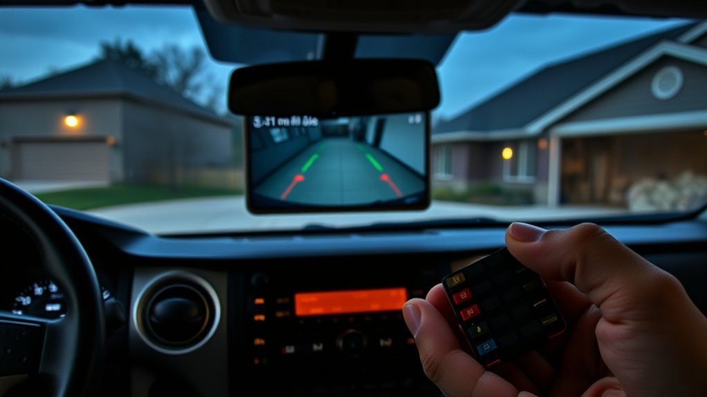
If your Tundra’s backup camera glitches, start by disconnecting the battery for about five minutes to clear stored error codes and reset the camera module; this often restores functionality immediately. You’ll reconnect power, then engage reverse to verify camera operation. Use diagnostic tools promptly if the fault returns: a scan will reveal codes like B15 D8, which pinpoints communication failures in the camera network. If aftermarket gear (Apple Play, for example) was added, uninstall it before running diagnostics—these devices can sever data lines and trigger recurring errors. Work methodically: isolate aftermarket modules, clear codes, and re-scan. Document any persistent fault codes and their timestamps so you can reclaim control without guesswork. This approach frees you from reliance on repeated trial-and-error and gives you a clear path to function restoration or informed service escalation. Keep tests short, targeted, and repeatable until the camera reports clean status.
Check Backup Camera Power and Fuses
After you’ve cleared codes and ruled out module-side faults, verify the camera’s power feed and fuses before chasing other causes. You’ll start by locating the correct fuse per the owner’s manual; accurate fuse identification prevents wasted effort. Pull the fuse and inspect it visually, then test with a multimeter for continuity. Next, back-probe the camera’s power pin with the vehicle in reverse; you should see ~12V. Lack of voltage signals a circuit interruption.
| Check | Tool | Expected |
|---|---|---|
| Fuse identification | Owner’s manual, multimeter | Intact fuse, continuity |
| Camera feed | Multimeter (voltage) | ~12V when in reverse |
| Reverse lights | Visual/test | Illuminate with reverse engaged |
If you have continuity but no voltage, trace upstream to the reverse-light circuit or relay. If voltage exists but camera stays dead, log error codes and pursue software updates or module-level faults. Maintain a methodical approach; regain control by eliminating each power continuity failure.
Inspect Wiring, Connectors, and Hinge Chafing
Start by visually tracing the camera harness from the tailgate into the body, looking for cuts, abrasions, or pinched sections where movement can break conductors. You’ll assess wiring integrity by inspecting insulation for nicks, exposed strands, and crushed areas, especially through hinge zones. Open connectors and inspect pins for connector corrosion, green/white deposits, or pitting that interrupts continuity. Move the tailgate while observing the harness; hinge chafing is progressive—look for worn spots where rubbing removed protective sheathing.
Secure the camera mount and confirm alignment; a loose bracket can strain wires. If you find damaged conductors, plan a splice using heat-shrink and solder or replace the harness section to restore mechanical strength. Clean mildly corroded terminals with contact cleaner and a small brush; replace heavily corroded connectors. Finally, confirm power at the camera connector with a multimeter while in reverse to verify repaired wiring integrity before reassembly.
Test the Camera: Bench and Tap Tests
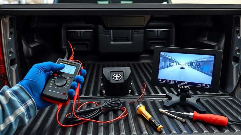
Start by bench testing the camera: disconnect it and apply a 12V power source to confirm it shows an image independent of the truck wiring, and use a multimeter at the vehicle connector to verify ~12V is present when in reverse. If the camera won’t power on on the bench it’s likely failed and needs replacement. For intermittent issues, perform a tap test—gently tap the housing while observing the image; flicker or return of the picture indicates a loose internal connection.
Bench Testing Procedure
Bench test the backup camera by powering it outside the vehicle to isolate it from the truck’s wiring and confirm its operation. Verify camera compatibility and wiring standards first: check the camera’s voltage spec with a multimeter (typically 12V) and confirm the connector pinout matches your monitor. Inspect the harness for frays, corrosion, or loose pins before applying power. Use a regulated 12V bench supply and a known-good video monitor or substitute camera for comparison. Observe the image for stable output; note color, sync, and noise. If you see no image, swap in the known-good camera to rule out monitor issues. Document findings—working, intermittent, or dead—to guide replacement or deeper diagnosis.
Tap Test Diagnostics
One quick way to pinpoint intermittent faults is to perform a tap test: with the camera powered and the display active, gently tap or wiggle the camera housing and harness while watching the image for momentary dropouts, noise, or color shifts. You’ll document behavior during taps, noting any reproducible artifacts that indicate loose contacts or internal failure. Bench test the camera by powering it off-vehicle to separate wiring faults from camera faults. Use a multimeter to confirm ~12V at the power input during reverse. Inspect for physical damage or moisture intrusion that undermines connection stability. This methodical camera troubleshooting lets you liberate the system from guesswork and target repairs or replacement confidently.
| Step | Action | Expected Result |
|---|---|---|
| 1 | Power camera | Stable image |
| 2 | Tap housing | Momentary dropout if faulty |
| 3 | Wiggle harness | Noise if connector loose |
| 4 | Bench power | Camera functions if wiring bad |
| 5 | Measure 12V | Confirms power supply |
Test Head Unit Input and Signal Path
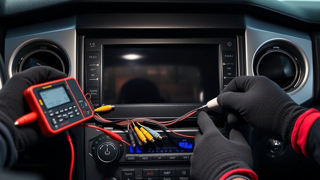
Start by verifying the reverse signal voltage at the head unit; with the truck in reverse you should measure about 12V on the camera trigger wire. Then trace the video signal path from the camera connector through the harness to the head unit, checking continuity and inspecting for damage or corrosion at each splice and connector. If multiple inputs exist, test each input and consider a factory reset to rule out software faults.
Verify Reverse Signal Voltage
When you test the reverse signal voltage, set your multimeter to DC volts and measure at the camera input while the truck is in reverse, expecting roughly 12V if the reverse lights are active; perform signal troubleshooting and voltage measurement deliberately to free yourself from guesswork. Probe the head unit input; if you see ~12V the power side is good. If not, check reverse light circuit and wiring continuity, referencing the wiring diagram. Inspect connectors for damage or looseness and repair faults to restore autonomy over your vehicle systems.
| Step | Target | Expected |
|---|---|---|
| Measure | Camera input | ~12V |
| Verify | Reverse lights | 12V present |
| Inspect | Wiring/connectors | Continuity, no damage |
| Reference | Wiring diagram | Correct wire ID |
Trace Video Signal Path
Begin by confirming the head unit actually receives the camera feed: with the truck in reverse, set your multimeter to DC volts and probe the camera input at the head unit harness for ~12V, verify the video pin (typically a RCA/video lead) shows continuity back to the camera, and consult the wiring diagram to guarantee each conductor (power, ground, video, and any trigger wire) is correctly routed and pinned. Next, disconnect the camera at the rear and test its output while in reverse to confirm it’s powered. If the head unit shows no video, inspect wiring for cuts, corrosion, or poor pins. Also verify head unit camera input settings and check for signal interference or misrouting that degrades image or camera alignment.
- Verify 12V and continuity
- Test camera output at rear
- Inspect harness and pins
- Confirm settings and interference
Diagnose Software and Aftermarket Conflicts
If you’ve added aftermarket modules like Apple CarPlay, check them first for data-bus conflicts because these installs can interrupt the camera’s communication and trigger errors such as B15 D8. Verify software compatibility between the head unit firmware and any aftermarket installation before proceeding. Run a focused diagnostic scan immediately after modification to detect communication errors on CAN or LVDS lines.
If you find faults, isolate the module: disconnect power and data leads, then perform a battery reset by unplugging the negative terminal for a few minutes to clear residual errors. Inspect wiring for damaged or misrouted data conductors; improper handling during install/uninstall often causes intermittent failures. Re-scan the network after each change to confirm resolved codes.
Adopt a systematic workflow: document changes, test after each intervention, and monitor for recurrences. This method frees you from guesswork and restores reliable backup camera function without replacing hardware prematurely.
Replace Parts: Camera, Harness, or Head Unit
Because internal camera failures are common—especially with aftermarket units, you’ll often start by swapping the camera itself to quickly rule out a faulty imager, then inspect the harness and head unit if the problem persists. You’ll choose a replacement verified for camera compatibility with your Tundra and bench-test it before installation. Next, inspect the wiring harness for corrosion, pin damage, or intermittent connections; test for 12V at the camera connector with a multimeter while another person shifts into reverse. If voltage is absent or unstable, plan wiring upgrades or harness replacement to restore reliable power and signal paths. Finally, if camera and harness check out, diagnose the head unit’s camera input and replace it if diagnostics show no signal output.
Start by swapping a verified camera, bench-test it, then inspect harness voltage and head unit input for faults.
- Swap camera (confirm camera compatibility, bench-test).
- Visually inspect harness (replace if damaged).
- Measure connector voltage (12V in reverse).
- Replace head unit if input fails.
Proceed methodically to reclaim control of your vehicle systems.
Preventive Checks: Seals, Lens, Firmware, Recalls
Although a failed camera often looks like a complex electrical fault, regular preventive checks on seals, lens, firmware, and recalls will cut failures and diagnostic time, so inspect the rubber and gasket seals for cracks or compression, wipe the lens with a lint-free cloth and isopropyl solution, verify firmware level against the manufacturer’s release notes and apply updates per the owner’s manual, check Toyota recall databases for any outstanding campaigns affecting the backup camera, and confirm all wiring connections are secure and corrosion-free to prevent intermittent or complete camera loss. Perform a routine seal inspection to stop moisture ingress and corrosion; replace compromised rubber or reseal mounting points. Use controlled lens cleaning—lint-free cloth, isopropyl alcohol, gentle motion—to remove grime without scratching optics. Verify firmware updates via the head unit or dealer; documented fixes can restore stability. Run recall checks online with your VIN and act on open campaigns promptly. Finally, torque and inspect connectors; liberation comes from proactive maintenance that minimizes surprises and keeps your system reliable.
Frequently Asked Questions
How to Fix Backup Camera Not Working?
Start by checking power and connections: you’ll use camera troubleshooting tips and wiring inspection techniques to spot damage, test 12V at the harness, clean the lens, verify reverse lights, and reset the system if needed.
What Is the Problem With Toyota Backup Cameras?
You’re facing camera calibration issues and faulty wiring connections causing intermittent or blank images; investigate if software glitches, damaged harnesses, loose connectors, or aftermarket installs disrupted data lines, then update firmware and secure or replace affected wiring.
Conclusion
Think of your Tundra’s backup camera like a lighthouse: when its bulb or wiring fails, the beam goes dark and navigation gets risky. You’ll methodically reset the system, verify power and fuses, trace wires through hinges, and bench-test or tap the camera to pinpoint faults. Replace faulty modules or the head unit, fix seals and firmware, then recheck. Restore the lighthouse—restore safe, reliable guidance for every reverse maneuver.