Use this guide to identify the trailer connector on a Toyota Tundra, install a 4-flat/7-way adapter, test each circuit, and fix common trailer-light or brake-output problems. Tundra wiring varies by model year, trim, tow package, and previous owner changes, so treat wire colors as clues—not proof—and always confirm each circuit with a tester before towing.
Quick Answer
A Toyota Tundra may have a 4-flat, a 7-way blade connector, or an OEM-style 7-pin/4-pin combo connector. A 4-flat handles basic lights only. A 7-way can also support electric brakes, reverse lights, and 12V auxiliary power, but only when those circuits are wired, fused, and tested correctly.
Key Takeaways
- Do not assume every Tundra has the same factory tow wiring. Verify your connector, model year, and equipment before buying parts.
- A Hopkins 37185/47185-style adapter can add a 7-way socket from a 4-flat, but the brake, 12V auxiliary, reverse, and ground leads still need the correct connections.
- Wire colors are common but not universal. Confirm each function with a multimeter, circuit tester, or trailer plug tester.
- Trailer brakes require a working brake controller output. A 4-flat-to-7-way adapter alone does not create brake control.
At a Glance
| Time Required | 30–90 minutes for an adapter; longer if adding brake-control or 12V power wiring |
| Difficulty | Easy for plug-in replacement; moderate for wiring extra circuits |
| Tools Needed | Socket set, screwdriver, circuit tester or multimeter, wire strippers/crimpers, heat-shrink connectors, zip ties, dielectric grease |
| Cost | Usually about $25–$100 for a connector/adapter; more if a brake controller, circuit breaker, or repair wiring is needed |
Warning: Before unplugging or replacing trailer wiring, park on level ground, set the parking brake, turn the key off, and disconnect the negative battery cable when the job requires electrical connector removal or wiring changes. Use the correct fuse or circuit breaker for any added 12V feed, and test trailer brakes at low speed in a safe area before road towing.
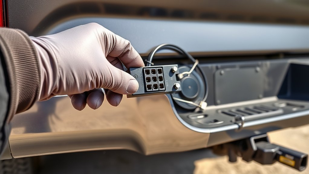
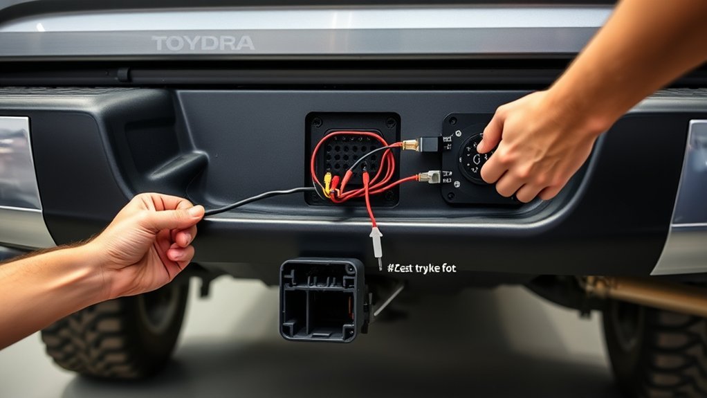
Identify Your Toyota Tundra Trailer Connector
Start at the rear bumper or hitch area. Depending on the Tundra’s year and equipment, you may see a 4-flat plug, a round 7-way blade socket, a combined 7-pin/4-pin connector, a capped factory harness, or aftermarket wiring from a previous owner. Toyota’s genuine 7-pin/4-pin connector is designed to work with the truck’s existing electrical system and allows either a 7-pin or 4-pin trailer connector when fitted to a compatible vehicle; verify fit by VIN, owner’s manual, or dealer parts lookup before assuming your truck has the same setup.
| Connector | What It Usually Supports | Best For |
|---|---|---|
| 4-flat | Ground, tail/running lights, left turn/stop, right turn/stop | Small utility trailers and boat trailers without electric brakes |
| 7-way blade | Basic lights plus possible electric brake output, 12V auxiliary, and reverse circuit | Campers, enclosed trailers, equipment trailers, and trailers with brakes |
| OEM 7-pin/4-pin combo | Both connector styles in one bumper-mounted assembly when the truck harness supports it | Drivers who tow different trailers |
| 4-flat-to-7-way adapter | Basic 4-flat lighting immediately; extra circuits only after wiring the added leads | Adding a 7-way socket to a truck that currently has only a 4-flat |
Note: A physical 7-way socket does not prove that electric brakes, 12V charging, or reverse lights are active. Each circuit must be connected, protected, and tested.
Tools, Parts, and Adapter Checklist
Gather the parts before opening the bumper connector. For a factory-style repair, use a Toyota-compatible 7-pin/4-pin connector assembly such as Toyota part PT725-34140 when it fits your truck. For an aftermarket conversion from a 4-flat to a 7-way plus 4-flat outlet, use a Hopkins 37185/47185-style adapter or an equivalent adapter with a mounting bracket and clearly labeled leads.
| Item | Purpose | Important Note |
|---|---|---|
| Toyota-compatible 7/4 connector or Hopkins adapter | Replaces or adds trailer plug access | Match the part to your truck and wiring goal |
| Socket wrench and screwdriver | Remove brackets, covers, and bumper hardware | Keep screws and clips in a tray |
| Multimeter, circuit tester, or 7-way tester | Verify wire and pin functions | Test by function, not color alone |
| Heat-shrink crimp connectors and wire strippers | Connect added brake, reverse, or auxiliary leads | Use weather-resistant connections under the truck |
| Dielectric grease and zip ties | Reduce corrosion and secure the harness | Use grease lightly; do not pack dirty terminals |
Pro Tip: Hopkins instructions for this style of adapter identify wires by function and warn that color coding is not standard across every manufacturer. Confirm the circuit with a tester before connecting it.
[Products Worth Considering]

These TPE door anti‑kick pads provide durable, water‑resistant protection for Toyota Tundra doors from 2022 to 2026. They fit precisely, are easy to install with double‑sided tape, and can be cleaned simply with water. The pads guard against scuffs and impacts while preserving the door's appearance and smooth operation.

The Pigenius windshield sunshade protects your Tundra's interior from heat and UV damage while keeping the cabin cool. Its accordion design folds easily for storage and quick setup, and the triple‑laminate construction provides durable, reflective protection. Ideal for long trips and daily commutes, it guards dashboards, seats, and steering wheels from sun‑related wear.

Upgrade your Toyota's front bumper with this premium license plate bracket that fits US and Canada plates perfectly. Made from heavy‑duty, rust‑proof plastic, it protects your paint and stays street legal. The kit includes six unique screws and a wrench for quick, tool‑free installation, ensuring a secure mount without scratches.
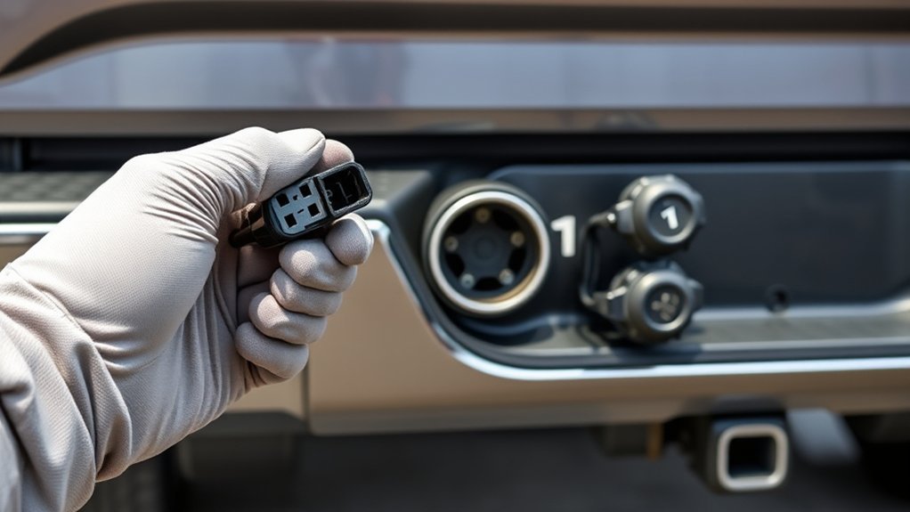
Remove the Factory Connector and Bracket Safely
Park the truck on level ground, set the parking brake, and make sure the trailer is unplugged. If you are removing the connector assembly or changing wiring, disconnect the negative battery cable first. Do not pull on the harness wires; release connector locks and pull on the connector body.
- Inspect the rear bumper or hitch bracket and locate the existing 4-flat, 7-way, or capped factory harness.
- Remove the mounting screws or release the retaining clips while supporting the connector body.
- Press the connector release tab and pull the plug straight out. Avoid twisting the connector or bending pins.
- Inspect the terminals for corrosion, green residue, bent blades, melted plastic, or loose pins.
- Clean the cavity with electrical contact cleaner and a small nylon brush if the terminals are dirty.
- Repair damaged wires before installing the new connector. Do not reuse wiring with exposed copper, cracked insulation, or heat damage.
Toyota’s accessory installation guidance for the Tundra emphasizes electrical safety, connector handling, harness protection, and functional verification. That same approach applies whether you are using an OEM connector or an aftermarket adapter.
Install the Adapter and Align the 4-Flat/7-Way Connection

If you are installing an OEM-style Toyota 7/4 connector, connect the truck’s factory 7-pin harness to the connector assembly, lock the connector in place, mount it in the bumper opening or bracket, then perform a functional test.
If you are installing a Hopkins 37185/47185-style adapter from an existing 4-flat, the 4-flat plug supplies the basic lighting circuits, but the added 7-way functions need separate attention. Connect only the circuits your trailer needs, and cap unused leads with sealed ends so they cannot short against the frame.
| Adapter Lead | Typical Function | Connection Guidance |
|---|---|---|
| White | Ground | Attach to a clean, bare metal frame ground with a ring terminal |
| Blue | Electric brake output | Connect only to a properly installed brake controller output |
| Black or red | 12V auxiliary / battery charge feed | Run through the correct fuse or circuit breaker near the battery |
| Purple | Reverse / backup circuit | Connect only if the trailer needs reverse lamps or a reverse-lockout solenoid |
| Brown, yellow, green | Tail/running, left stop/turn, right stop/turn | Usually supplied through the 4-flat, but still test each function |
- Hold the adapter so the 4-flat and 7-way sockets face the correct direction and the dust covers can open freely.
- Seat the 4-flat connection fully. Pins should be straight, clean, and parallel.
- Fasten the mounting bracket so the connector does not move when a trailer plug is inserted or removed.
- Route extra wires away from the exhaust, driveshaft, spare tire winch, suspension travel, and sharp metal edges.
- Secure the harness with zip ties, leaving enough slack for normal frame movement but no dangling loops.
[Products Worth Considering]

Upgrade your vehicle's cargo capacity with these heavy‑duty aluminum roof crossbars that lock securely and reduce wind noise. The aerodynamic design and adjustable width provide a quiet, stable platform for luggage up to 260 lb, while the easy‑install kit and labeled front and rear bars simplify setup. Ideal for Toyota Grand Highlander and Lexus TX models from 2024‑2026 with flush side rails.

Upgrade your RAV4 roof rack with these heavy‑duty aluminum crossbars featuring an anti‑theft lock and tie‑down loops for secure cargo transport. The matte‑powder‑coated bars resist corrosion and reduce wind noise, while easy installation fits existing rails without drilling. Ideal for bike mounts, roof boxes, kayaks and more.

Tundra Trailer Wiring Harness: This multi-tow tundra trailer adapter compatible with Toyota Tundra 2003, 2004, 2005, 2006, easily install both 4 pin flat and rv 7 pin trailer connector on your vehicle
Test Each Pin: Turn, Brake, Tail, Reverse, and 12V Power
Use a 7-way tester, circuit tester, or multimeter before connecting the trailer. Put the truck in Park, set the parking brake, and keep helpers clear of the vehicle. When testing lights, turn on one function at a time so you can identify crossed circuits quickly.
Note: The clock positions below describe a common North American RV-style 7-way blade socket when viewed from the mating face of the vehicle socket with the lid/latch at the top. Positions can appear reversed from the wire side, so verify against the adapter diagram and a tester.
| 7-Way Position | Function | Typical Wire Color | How to Test |
|---|---|---|---|
| 11 o’clock | Tail/running/marker lights | Brown | Turn on parking lights; tester should show steady power |
| 1 o’clock | 12V auxiliary / battery charge | Black or red | Check for fused 12V power if this circuit is installed |
| 3 o’clock | Right turn and right brake | Green | Right signal should flash; brake should show steady power |
| 5 o’clock | Electric brake output | Blue | Use the brake controller manual slide; output should vary with gain |
| 7 o’clock | Ground | White | Check continuity to clean chassis ground |
| 9 o’clock | Left turn and left brake | Yellow | Left signal should flash; brake should show steady power |
| Center | Reverse / backup | Purple | Power should appear only when reverse is selected, if wired |
For a 4-flat connector, the usual functions are simpler: white is ground, brown is tail/running lights, yellow is left turn/stop, and green is right turn/stop. Because color coding can vary, confirm each circuit by function before splicing or repairing wiring.
Troubleshoot Common Issues: Fuses, Grounds, Stiff Plugs, and Marker Lights
Trailer wiring problems usually come from four places: a blown fuse, a bad ground, corrosion in the connector, or crossed trailer-side wiring. Work from the truck connector first, then move to the trailer plug and trailer lights.
| Symptom | Likely Cause | Fix |
|---|---|---|
| No trailer lights at all | Poor ground, disconnected plug, dead fuse, or no truck-side power | Test the ground first, then test each truck-side pin before blaming the trailer |
| Only marker/tail lights fail | Tail/marker fuse, brown-wire circuit, corroded terminal, or overloaded lamps | Check the trailer tail/running light circuit and fuse chart; inspect side marker wiring |
| Turn signal flashes both sides | Weak ground or crossed left/right trailer wiring | Clean the ground point and test left/right pins separately |
| Trailer brakes do not work | No brake controller output, bad blue wire, poor ground, or trailer brake issue | Test the 7-way brake-output pin using the controller manual slide |
| 7-way plug is hard to insert | Bent blade, dirt, corrosion, or misaligned connector housing | Clean contacts, straighten damaged pins carefully, and remount the socket squarely |
| 12V auxiliary does not work | Missing charge wire, blown fuse/circuit breaker, or unconnected adapter lead | Confirm fused battery feed at the 7-way and verify wire size for the load |
Federal lighting rules for trailers fall under FMVSS No. 108, which covers lamps, reflective devices, and associated equipment. If marker, clearance, brake, or turn lights do not work correctly, fix the wiring before towing on public roads.
Does Your Tundra Need a Brake Controller or 12V Feed?
A 4-flat connector does not provide electric brake control. If your trailer has electric brakes, the 7-way brake pin must be connected to a brake controller output. Some Tundras are equipped with an integrated trailer brake controller; others need an aftermarket controller installed with the correct power, ground, brake signal, and output wiring. Toyota’s Tundra accessory verification procedure checks the electric trailer brake circuit only when a brake controller is installed.
A 12V auxiliary feed is also optional unless your trailer needs it for battery charging, interior lights, a breakaway battery maintenance charge, or accessories. Run this lead from a protected power source with the correct fuse or circuit breaker near the battery. Do not connect an unfused battery wire directly to the 7-way socket.
Warning: Brake-controller and 12V charge wiring can affect stopping distance and electrical safety. If you are not comfortable selecting wire gauge, routing battery power, or setting brake-controller gain, have a qualified trailer or automotive electrical technician complete that part of the installation.
[Products Worth Considering]
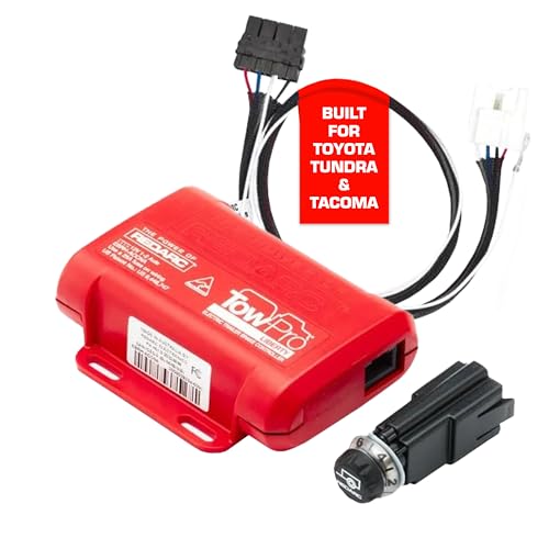
Proportional Mode Brake Kit for Everyday Towing: The Tow-Pro Liberty delivers Proportional Mode braking for smooth on-road control. Easy to install and use, the system reduces push and pull for ultimate towing confidence on roads and highways

Proportional Mode Brake Kit for Everyday Towing: The Tow-Pro Liberty delivers Proportional Mode braking for smooth on-road control. Easy to install and use, the system reduces push and pull for ultimate towing confidence on roads and highways

【Applicable Models】The Brake Controller Harness is compatible with 2003-2014 Toyota Tundra(EXCEPT 2004), 2003-2013 4Runner, 2003 -2021 land Cruiser, 2003-2022 sequoia, 2005-2015 Tacoma, 2010-2020 Lexus GX 460, 2003 -2009 Lexus GX 470, 2003-2007 Lexus LX 470, 2008-2020 lexus LX 570
Adapter Compatibility: 7-to-4, 4-to-7, and Mixed-Plug Options
Choose the adapter based on the trailer plug and the functions the trailer actually needs. Matching the physical plug is only half the job; the truck must also supply the required circuits.
7-Pin to 4-Flat
A 7-pin-to-4-flat adapter is the easiest setup when the Tundra already has a working 7-way and the trailer only needs basic lights. Plug the adapter into the 7-way socket, connect the trailer’s 4-flat, then test tail/running lights, left turn/stop, right turn/stop, and hazards. The 4-flat trailer will not use the 7-way brake, reverse, or 12V auxiliary circuits.
4-Flat to 7-Blade
A 4-flat-to-7-blade adapter gives you a 7-way-shaped socket, but the 4-flat portion only carries basic lighting and ground. To make the 7-way fully functional, wire the ground, brake controller output, 12V auxiliary feed, and reverse circuit as needed. If the trailer has electric brakes, do not tow until the brake controller output has been tested.
Mixed Connector Adapters
Mixed connector adapters are useful when you tow more than one trailer. A combined 7-way and 4-flat outlet saves time because you do not need a loose adapter for every trip. Keep the dust covers closed when the sockets are not in use, rinse off road salt, and inspect the blades before each towing season.
Maintenance Checklist for Reliable Towing
- Test the trailer connector before long trips and after any wiring repair.
- Clean corrosion from terminals instead of forcing the plug into the socket.
- Use a small amount of dielectric grease on clean terminals to help reduce corrosion.
- Check the trailer ground connection whenever lights behave strangely.
- Secure loose harness sections so they cannot touch the exhaust, suspension, or driveshaft.
- Replace damaged dust covers because water inside the connector causes repeat failures.
- Confirm trailer weight, tongue weight, and load ratings in the Tundra owner’s manual before towing.
Frequently Asked Questions
How do I wire trailer lights to my Toyota Tundra?
Start by identifying the truck-side connector, then test each circuit by function. A 4-flat normally uses white for ground, brown for tail/running lights, yellow for left turn/stop, and green for right turn/stop. A 7-way adds circuits for electric brakes, 12V auxiliary power, and reverse lights when those leads are installed.
What color trailer wires go where?
Common 4-flat colors are white ground, brown running lights, yellow left turn/stop, and green right turn/stop. Common 7-way added colors include blue for electric brakes, black or red for 12V auxiliary power, and purple for reverse. Always verify by function because manufacturers do not use one universal color code.
Can I tow a trailer with electric brakes using only a 4-flat connector?
No. A 4-flat connector supports basic trailer lighting and ground only. Electric trailer brakes need a 7-way brake-output circuit connected to a brake controller. A 4-flat-to-7-way adapter must have the blue brake-output lead wired correctly before the trailer brakes will work.
Why do my trailer lights work on one trailer but not another?
That usually means the truck connector works but the second trailer has a wiring, bulb, ground, or plug problem. Test the truck first, then test the trailer plug. If the trailer lights flicker or cross-feed, clean the trailer ground and inspect the wiring near the tongue.
Should I put dielectric grease inside the trailer connector?
Use a light coating on clean terminals to help reduce corrosion. Do not pack a dirty or corroded connector full of grease. Clean the terminals first, repair loose or damaged pins, then apply a small amount before closing the dust cover.
Conclusion
A Toyota Tundra trailer connector is simple once you separate the basic lighting circuits from the added 7-way circuits. Identify the truck-side connector, choose the right OEM connector or adapter, secure the housing, then test ground, tail/running lights, left turn/stop, right turn/stop, reverse, 12V auxiliary power, and brake-controller output. If anything fails, start with fuses, grounds, corrosion, and pin orientation before replacing parts.
Sources
- Toyota Genuine 7-Pin and 4-Pin Trailer Connector — supports fitment and function notes for Toyota’s 7/4 connector.
- Toyota Tundra Trailer Wire Harness Installation Instructions — supports safe connector handling and functional verification steps.
- Hopkins 47185 Instruction Sheet — supports adapter wire functions and color-code caution.
- SAE J2863 Automotive Trailer Tow Connector Standard — supports the seven-position automotive/RV trailer connector reference.
- 49 CFR 571.108 / FMVSS No. 108 — supports trailer lighting and lamp-equipment compliance context.